
Device for desorption and ionization

a technology of ionization and desorption, which is applied in the direction of separation process, particle separator tube details, instruments, etc., can solve the problems of difficult modification of current commercial ion sources, high speed of implementing techniques, and uncertain sampling area of analyte, etc., to facilitate the location of sampling areas, enhance the ionization efficiency of sources, and stabilize the corona stream

Active Publication Date: 2012-08-14
SHIMADZU CORP
View PDF5 Cites 30 Cited by
  • Summary
  • Abstract
  • Description
  • Claims
  • Application Information

AI Technical Summary

Benefits of technology

[0012]The corona beam formed at the tip of the metal tube extends out for 8 to 12 mm and goes through a ring electrode which serves as the counter electrode for the corona discharge. The corona beam appears to be visible with a sharp tip at the very end. Hence, the sampling area can be observed when the tip of the beam scans across the surface of a solid sample, which facilitates locating of the sampling areas and helps avoid any interference from the uninterested portion of the sample.
[0013]Optionally, water or other organic solvents can be infused into the metal tube through the heater in order to both stabilize the corona stream and enhance the ionization efficiency of the source.
[0014]The desorption and ionization source mentioned in this invention generates the visible corona beam under atmospheric pressure using voltage and current supplied by a common commercial ion source. The visible corona beam has greatly facilitated locating and mapping the sample surface.

Problems solved by technology

However, the time consuming processes of sample pretreatment before conducting any analysis in a mass spectrometer prevent the techniques from being implemented on site with high speed.
One limitation for these corona discharge based methods is that the plasma is only visible at the tip of the discharge needle and therefore the sampling area for the analyte is very uncertain.
However, almost all the techniques described above with luminous plasma require high amplitude RF voltages and this makes the modification difficult for the current commercial ion source based on APCI and ESI which all use DC voltage for ionization.
This method though would need a chamber filled with He gas which increases the complexity of the source modification and also the temperature of the plasma is very high (400˜700° C.) that makes the control of experimental conditions difficult.

Method used


Image

  • Device for desorption and ionization
  • Device for desorption and ionization
  • Device for desorption and ionization

Examples


Embodiment Construction

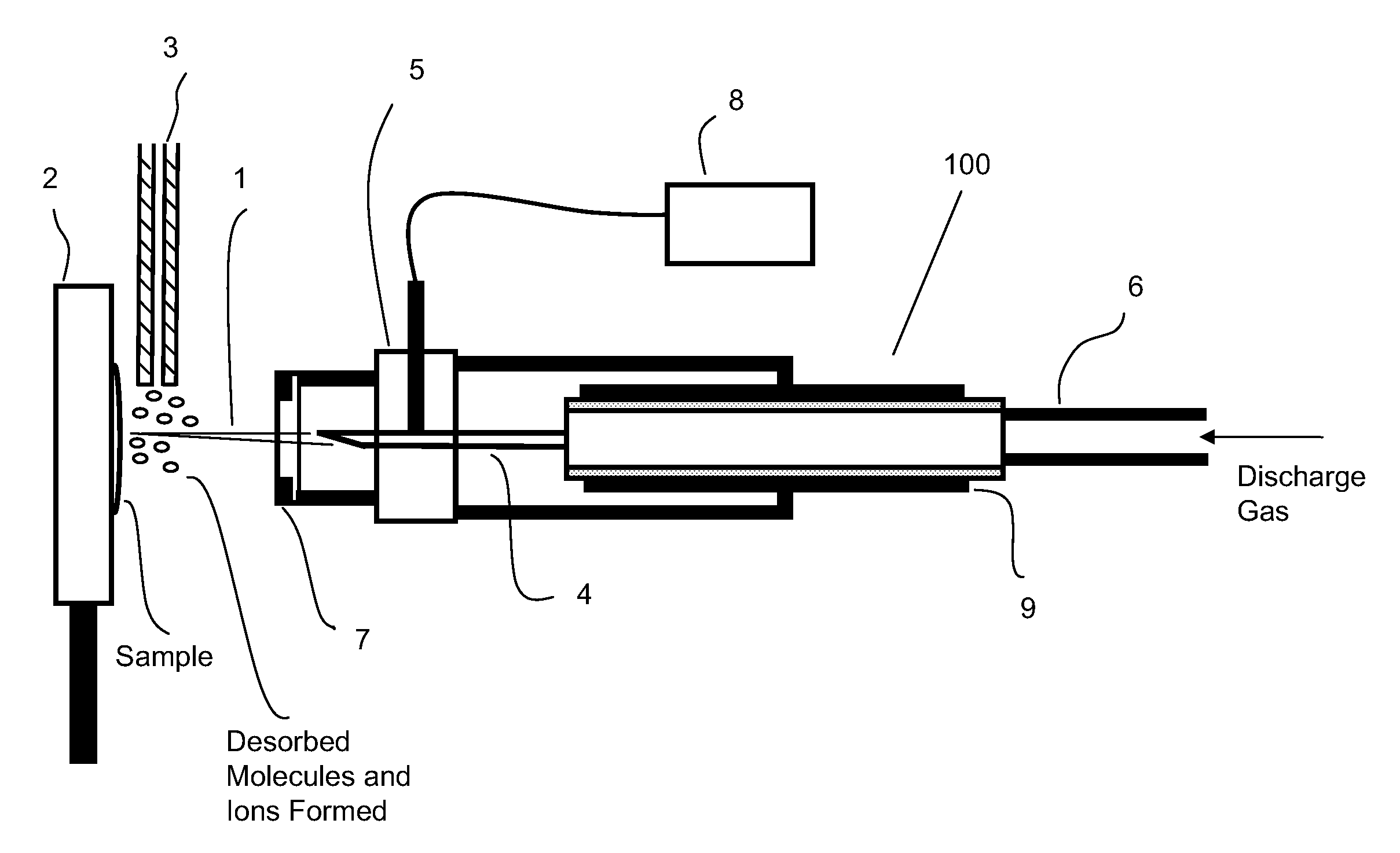
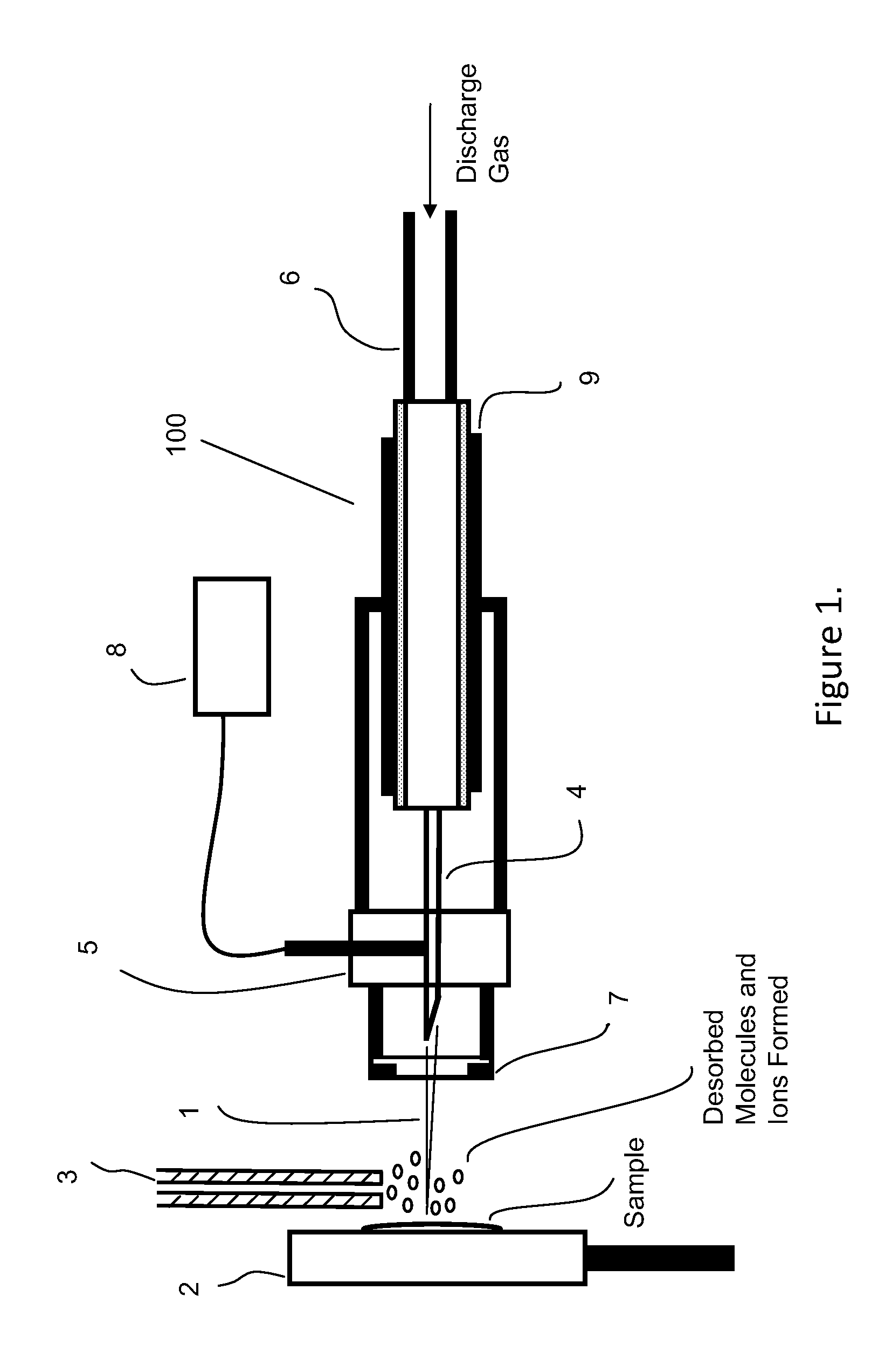
[0020]The schematics of the DCBI source is shown in FIG. 1 and it includes a sample probe 100 for generating the corona beam 1, a sample support 2 for placing the samples, and an ion inlet 3 for introducing the ions formed into a device capable of ion analysis. The corona beam 1 was formed by applying a direct current voltage (2˜5 kV) to the tip of the metal tube 4 when a stream of gas (preferably He) flows through the metal tube 4 at a rate ranging from 1 to 2 L / min. The supplied gas can be heated to 150˜350° C. before it reaches the sample support 2 for thermally desorbing the analytes. The desorbed gaseous species are ionized by interaction with energetic particles generated in the corona discharge under the atmospheric pressure. The ions formed are then delivered into a mass spectrometer or other devices through the ion inlet 3 for further analysis.

[0021]The solid analytes need to be thermally desorbed from the surface first. Therefore the samples normally are volatile or semi-v...


PUM


Abstract

The current invention involves a desorption corona beam ionization source / device for analyzing samples under atmospheric pressure without sample pretreatment. It includes a gas source, a gas flow tube, a gas flow heater, a metal tube, a DC power supply and a sample support / holder for placing the samples. A visible corona beam is formed at a sharply pointed tip at the exit of the metal tube when a stream of inert gas flows through the metal tube that is applied with a high DC voltage. The gas is heated for desorbing the analyte from solid samples and the desorbed species are ionized by the energized particles embedded in the corona beam. The ions formed are then transferred through an adjacent inlet into a mass spectrometer or other devices capable of analyzing ions. Visibility of the corona beam in the current invention greatly facilitates pinpointing a sampling area on the analyte and also makes profiling of sample surfaces possible.

Description

FIELD OF THE INVENTION[0001]The current invention generally relates to desorption and ionization technique under atmospheric pressure and room temperature, and more particularly to a device that utilizes a corona beam for desorption and ionization of the analytes.BACKGROUND OF THE INVENTION[0002]With the widespread use of Liquid Chromatography-Mass Spectrometry (LC-MS) systems for analyzing complex mixture of compounds around the world, ionization sources working under atmospheric pressure such as Electrospray Ionization (ESI) and Atmospheric Pressure Chemical Ionization (APCI) sources have been playing very important roles in the fields of food safety, environment protection and homeland security. However, the time consuming processes of sample pretreatment before conducting any analysis in a mass spectrometer prevent the techniques from being implemented on site with high speed. This issue was addressed and partially solved with the emergence of some pioneering direct analysis met...

Claims


Application Information

Patent Timeline
Patent Type & Authority Patents(United States)
IPC IPC(8): H01J27/08H05H1/24H01J49/04
CPCH01J49/168
Inventor SUN, WENJIANYANG, XIAOHUIDING, LI
Owner SHIMADZU CORP
Learn More