
LED light device

a technology of led light and diode, which is applied in the direction of semiconductor devices for light sources, discharge tubes luminescnet screens, lighting and heating apparatus, etc., can solve the problems of increasing inefficiency reducing the life reducing the etc., to achieve enhanced brightness of led light devices, enhance cooling air being, and maintain aesthetic appearance of led light devices

Inactive Publication Date: 2012-08-14
NINGBO FUTAI ELECTRIC CO LTD
View PDF4 Cites 20 Cited by
  • Summary
  • Abstract
  • Description
  • Claims
  • Application Information

AI Technical Summary

Benefits of technology

"The invention is a LED light device with a heat dissipating arrangement to prolong its lifespan. The device has a plurality of air guiding inlets that align with the heat dissipating channels to guide air flow and remove heat generated from the LEDs. The front sides of the heat dissipating fins are concealed by the air guiding member to maintain the aesthetic appearance of the LED light device. The air is guided to flow into the air guiding inlets to enhance cooling air for heat dissipation of the LEDs. The LED light device does not require altering its original electrical configuration and is an economic and efficient solution for removing heat and keeping its aesthetic appearance. The invention provides a solution for maintaining the brightness of LEDs while keeping the ambient temperature around them at a low level. No expensive or complicated structure is required for the invention."

Problems solved by technology

First, it consumes lower level of power for its low voltage requirement.
When the ambient temperature increases, the LED light device is increasingly inefficient.
In addition, the lifetime of the LED light device is greatly reduced if operated under high temperature.
That is to say, high temperature is destructive to the LED light device.
The problems of low brightness and well-controlled temperature requirement are neglected and remained unsolved.
However, during the heat dissipation of the heat sink, the air will flow turbulently so as to reduce the efficiency of the heat sink.
On the other hand, the LED light bulb cannot keep the overall aesthetic appearance when it incorporates the heat sink.

Method used


Image

  • LED light device
  • LED light device
  • LED light device

Examples


Embodiment Construction

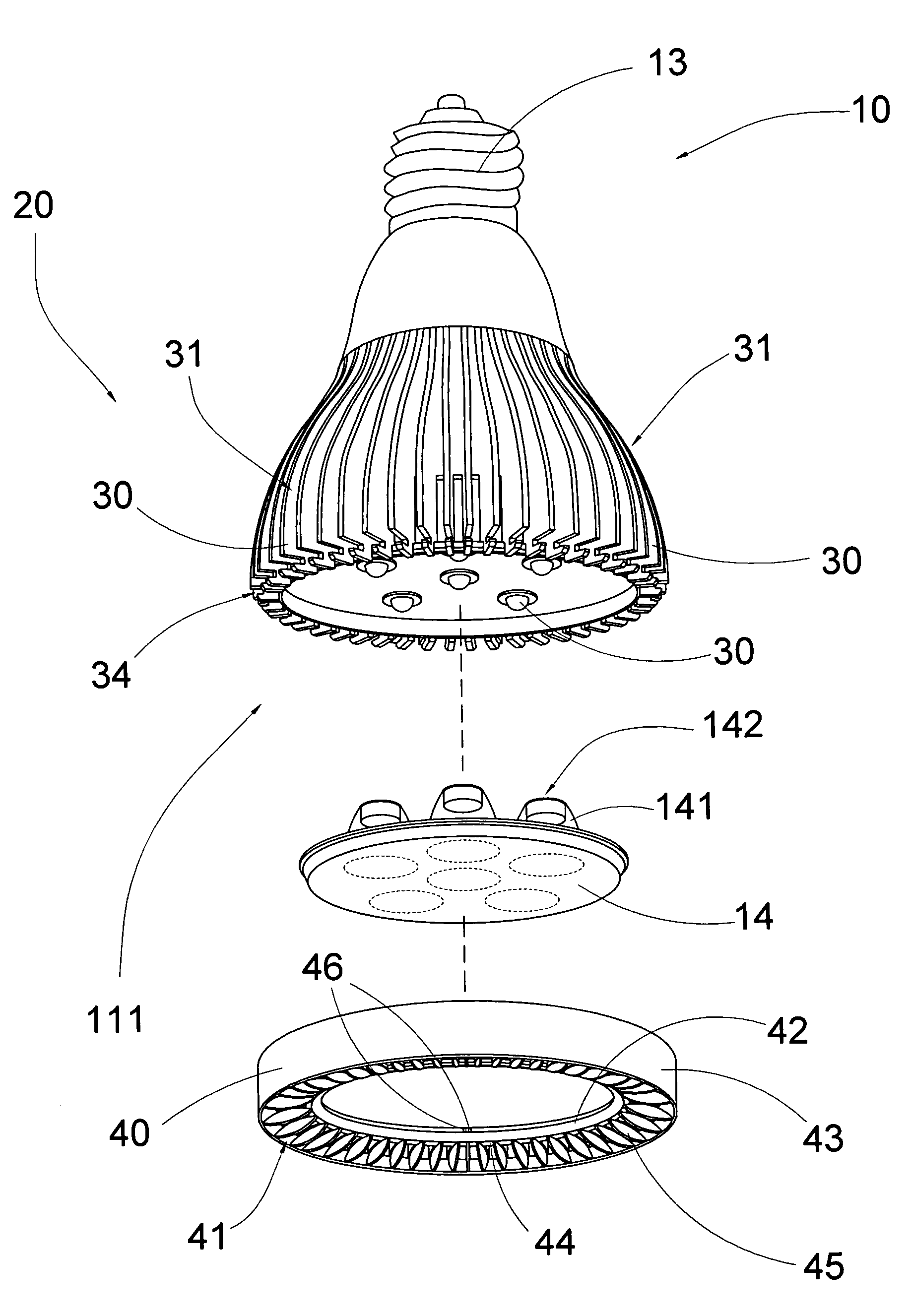
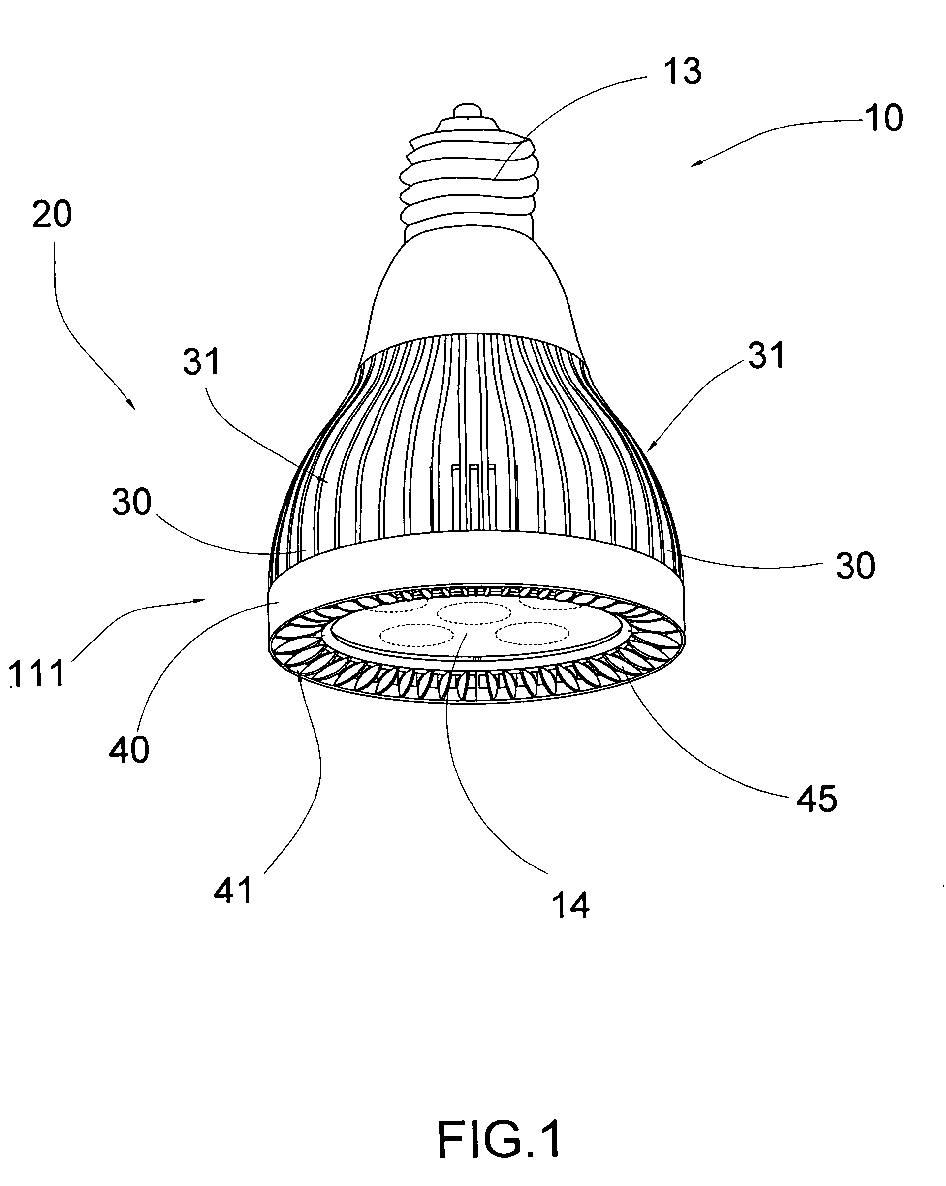
[0027]Referring to FIGS. 1 to 4 of the drawings, a LED light device according to a preferred embodiment of the present invention comprises a LED (light-emitting diode) assembly 10 and a heat dissipating arrangement 20. Accordingly, the LED light device of the present invention is embodied as a light bulb operatively coupling with an electrical socket within a light housing.

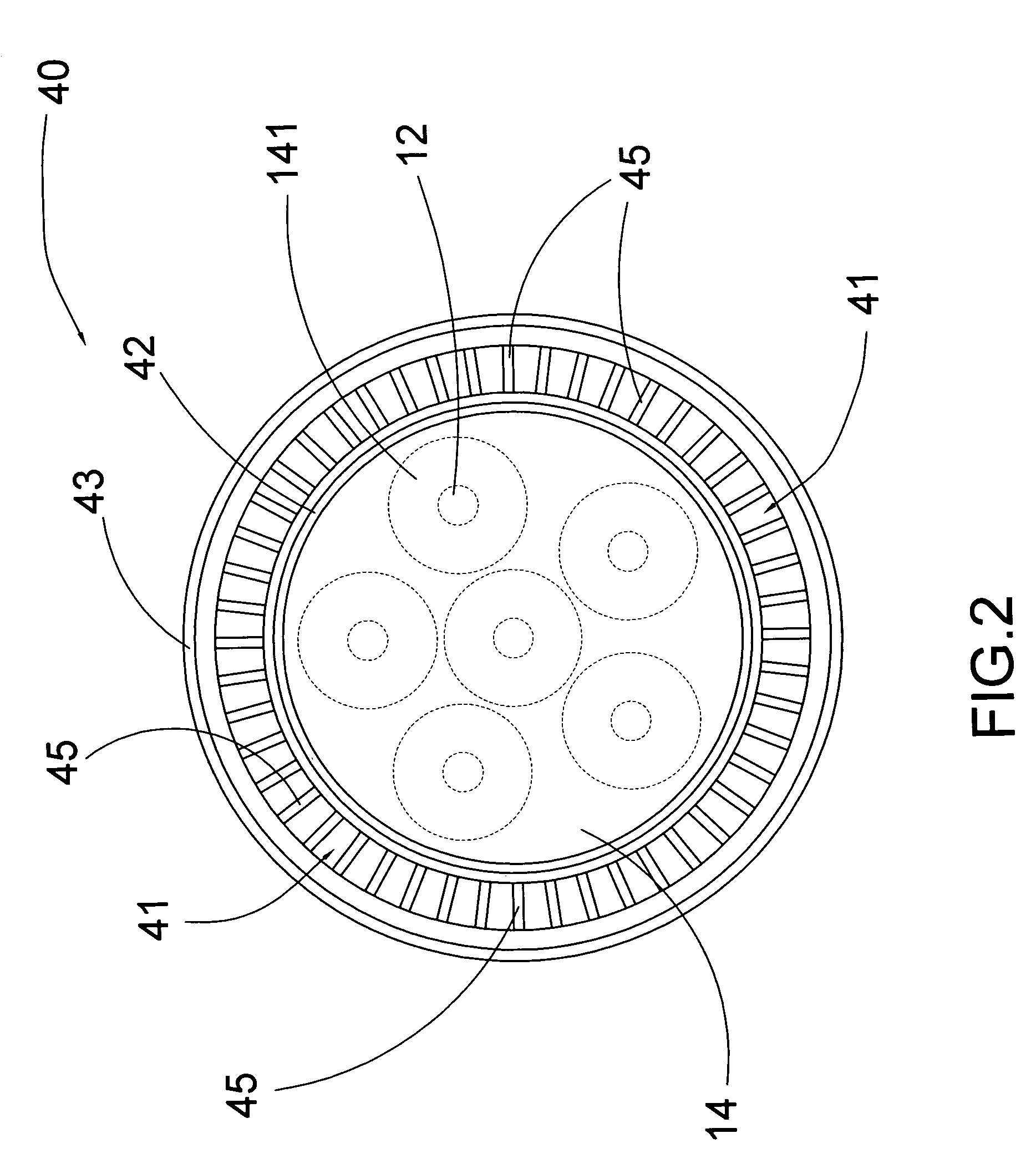
[0028]According to the preferred embodiment, the LED assembly 10 comprises a light body 11, one or more LEDs 12 supported at a front side 111 of the light body 11 for light generation, and a power inlet 13 operatively linked to the LEDs 12 for connecting a power source. Accordingly, there are six LEDs 12 orderly provided at the light body 11 for enhancing the light intensity of the LED assembly 10. Preferably, the LEDs 12 are diodes electrically coupled at a circuit board at the front side 111 of the light body.

[0029]The LED light assembly 10 further comprises a light dissipating lens 14 coupled at the front side ...


PUM


Abstract

A LED light device includes a light-emitting diode assembly including a light body and one or more LEDs supporting thereat, and a heat dissipating arrangement including a plurality of heat dissipating fins radially and outwardly extended from the light body to define a heat dissipating channel between every two of the heat dissipating fins, and an air guiding member coupled at the front side of the light body. Each of the heat dissipating channels has a front opening extended at the front side of the light body and an elongated side opening for dissipating heat generated from the LED assembly. An air guiding member has a plurality of guiding inlets aligning with the front openings of the heat dissipating channels respectively for guiding air flowing to the heat dissipating channels so as to effectively dissipating the heat from the LED assembly through the heat dissipating fins.

Description

BACKGROUND OF THE PRESENT INVENTION[0001]1. Field of Invention[0002]The present invention relates to a light-emitting diode (LED) device for lighting purpose, and more particularly to a LED light device with heat dissipating arrangement for effective heat convection and brightness enhancement features.[0003]2. Description of Related Arts[0004]LEDs are commonly used as lighting device and are becoming more and more popular for household use for the following reasons. First, it consumes lower level of power for its low voltage requirement. Second, it generates lower level of heat which is particular important in today's increasingly hot climate condition. Third, it is energy saving. Forth, it has a long lifetime under well-controlled operative temperature.[0005]Conversely, LED light device also has the following disadvantages. It has low level of brightness. When the ambient temperature increases, the LED light device is increasingly inefficient. In addition, the lifetime of the LED l...

Claims


Application Information

Patent Timeline
Patent Type & Authority Patents(United States)
IPC IPC(8): H05B33/00H01J61/52
CPCF21K9/17F21V29/773F21V29/83F21V5/007F21Y2101/02F21V29/89F21Y2105/001F21Y2105/10F21K9/27F21Y2115/10F21K9/232
Inventor QIU, FU JUN
Owner NINGBO FUTAI ELECTRIC CO LTD
Learn More