
Roll joint and method for a surgical apparatus

a surgical apparatus and roll joint technology, applied in the direction of rod connection, surgical forceps, applications, etc., can solve the problems of limited load carrying capacity, small axle, difficult assembly, etc., and achieve the effect of easy formation on a small scale and large features

Active Publication Date: 2012-08-21
INTUITIVE SURGICAL OPERATIONS INC
View PDF7 Cites 1121 Cited by
  • Summary
  • Abstract
  • Description
  • Claims
  • Application Information

AI Technical Summary

Benefits of technology

The solution provides a compact and rigid roll joint that maintains all degrees of freedom, including roll, pitch, and yaw, without the limitations of pulleys, enhancing the mechanical actuation and control of surgical instruments with improved load-carrying capacity and structural stiffness.

Problems solved by technology

These pulleys required very small axles, which were limited in load carrying capability and were difficult to assemble.
Further, these pulleys consumed a significant volume in the surgical instrument wrist in a manner that conflicts with making use of the same volume to stiffen the structure of the surgical instrument.

Method used


Image

  • Roll joint and method for a surgical apparatus
  • Roll joint and method for a surgical apparatus
  • Roll joint and method for a surgical apparatus

Examples


Embodiment Construction

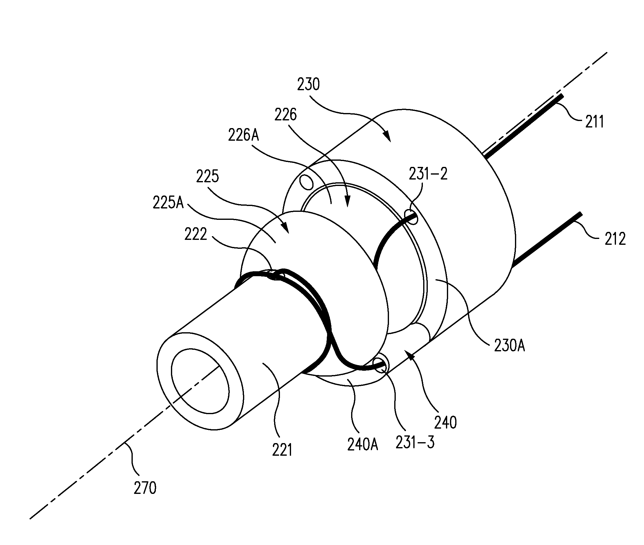
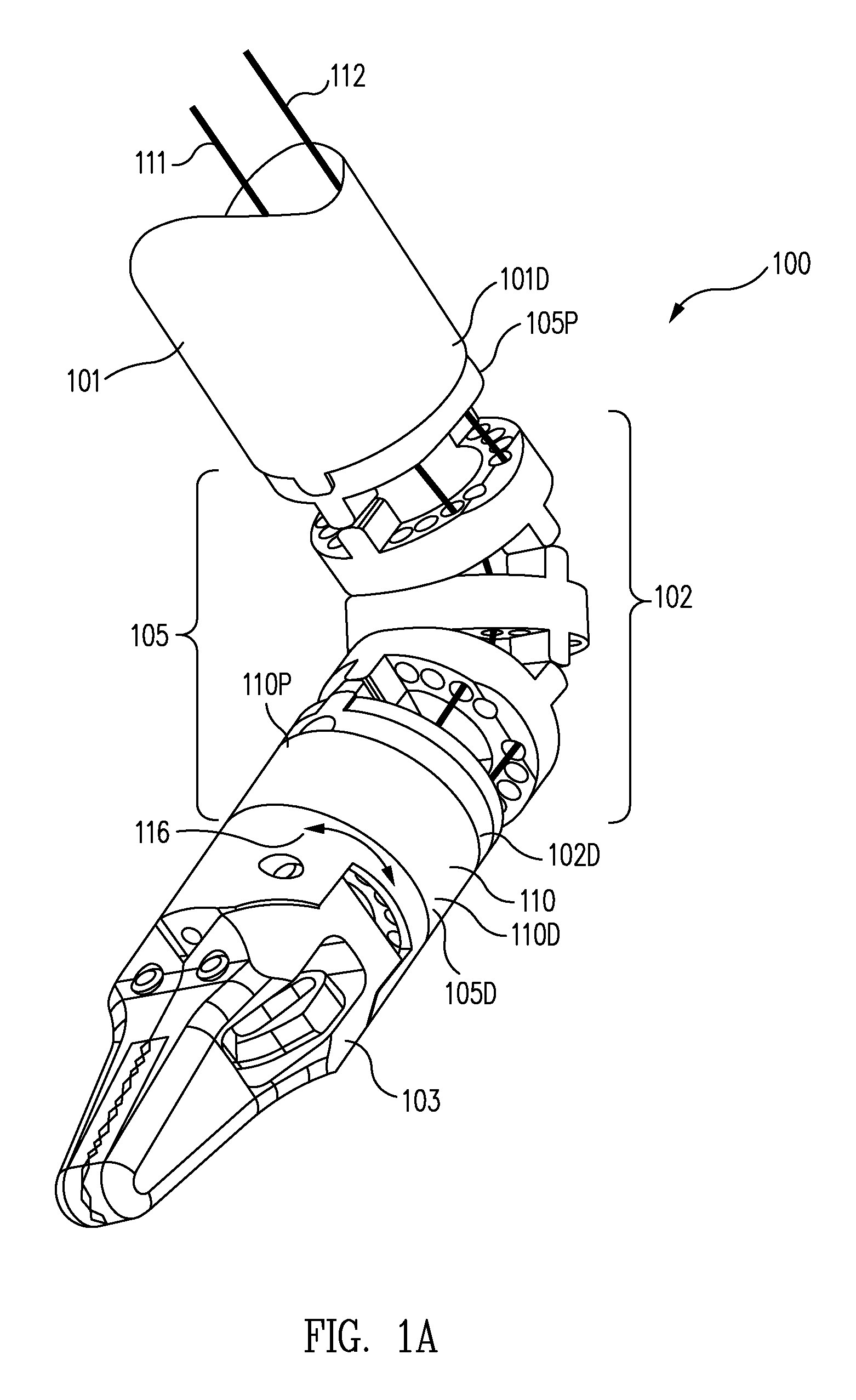
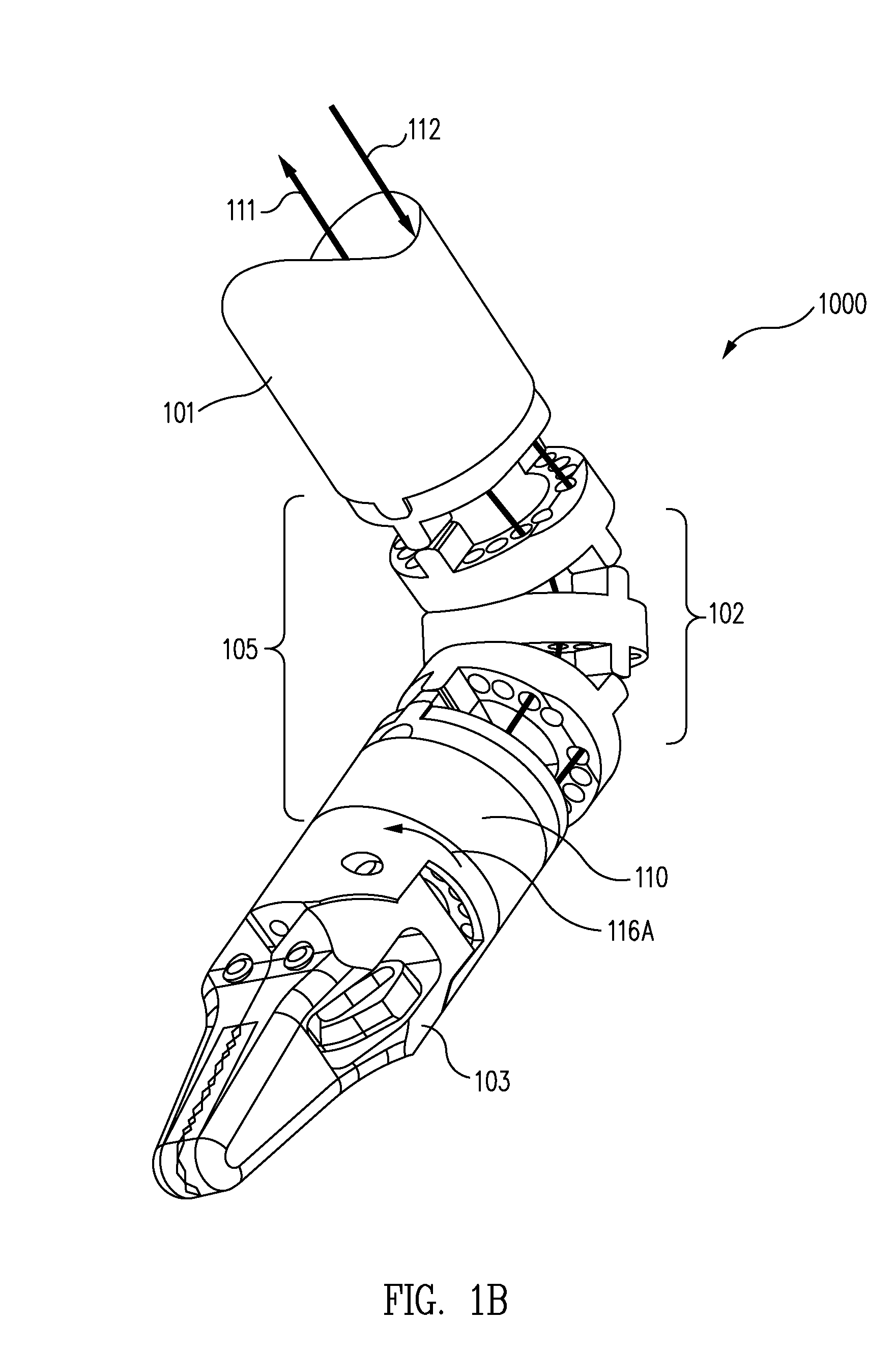
[0033]In one aspect, a robotic surgical system includes a surgical instrument 100 (FIG. 1A) that includes that includes a shaft 101. Shaft 101 is coupled to an end effector 103 by a wrist 105 that includes (1) a plurality of joints 102, and (2) a compact and rigid roll joint 110 that rotates in directions 116 around an axis that extends through the longitudinal center line. (See for example, axis 270 in FIG. 2A.) While in this example, roll joint 110 is mounted distally to plurality of joints 102, this is illustrative only and is not intended to be limiting. Roll joint 110 can be used at any locations where the attributes of roll joint 110 are beneficial.

[0034]As used herein, distal means a portion of an element furthest removed from the apparatus supporting surgical instrument 100, while proximal means a portion of that element closest to the apparatus. For example, wrist 105 has a proximal end 105P connected to a distal end 101D of shaft 101 and a distal end 105D connected to end ...


PUM


Abstract

A roll joint utilizes at least one tendon guide surface to guide actuator tendons for distal roll off and on their respective drums on a central shaft of the roll joint. The tendon guide surface turns the actuator tendon in an axial direction in a more compact space than might be required for a pair of pulleys, while using fewer parts with larger features more easily formed on a small scale.

Description

BACKGROUND OF THE INVENTION[0001]1. Field of the Invention[0002]The present invention relates generally to joints for surgical apparatus used in remote surgery, and more particularly to a roll joint for a surgical apparatus.[0003]2. Description of Related Art[0004]Minimally invasive telesurgical robotic systems increase a surgeon's dexterity when working within an internal surgical site, as well as allow a surgeon to operate on a patient from a remote location. In a telesurgery system, the surgeon is often provided with an image of the surgical site. While viewing a three-dimensional image of the surgical site on a suitable viewer or display, the surgeon performs the surgical procedures on the patient by manipulating master input devices of the system.[0005]The master input devices control the motion of a servomechanically operated surgical instrument. During the surgical procedure, the telesurgical robotic system can provide mechanical actuation and control of a variety of surgical...

Claims


Application Information

Patent Timeline
Patent Type & Authority Patents(United States)
IPC IPC(8): B25J17/02
CPCA61B17/29A61B19/2203A61B2017/00323A61B2017/2908A61B2017/2929Y10T74/20323A61B2019/2238A61B2019/2242Y10T403/32008Y10T74/20335A61B2019/2234A61B34/30A61B34/71A61B2034/305A61B2034/306
Inventor ROGERS, THEODORE W.WILLIAMS, MATTHEW R.
Owner INTUITIVE SURGICAL OPERATIONS INC
Learn More