Phase Object Identification Device and Method

a phase object and identification device technology, applied in the field of phase object identification devices and methods, can solve the problems of failure to create any cells, unfit observation of dyed cells, and scarcity of donors and rejections

Inactive Publication Date: 2011-02-24
JAPAN SCI & TECH CORP
View PDF4 Cites 1 Cited by
  • Summary
  • Abstract
  • Description
  • Claims
  • Application Information

AI Technical Summary

Benefits of technology

[0018]The phase object identification device and method according to the present invention are essentially different in technical idea from the prior art in which the phase modulation pattern itself of a phase object to be identified is identified by converting the change in phase of light caused by the phase object into the change in light intensity, and provided to detect the correlation between a phase to be identified and a known phase object for identifying the phase object to be identified. Furthermore, the phase object identification device and method according to the present invention also have a big feature in that the correlation between a phase to be identified and a known phase object is detected by the calculation of optical correlation with the use of holography.
[0019]The holography refers to a technique which is capable of recording the amplitude (intensity) and phase of light, which is able to record phase information on a known phase object directly as a hologram. More specifically, when a recording medium is irradiated with object light that is phase-modulated by a known phase object and reference light so as to overlap the object light and the reference light with each other in a hologram recording layer of the recording medium, the hologram formed by interference between the object light and the reference light can cause a photoreaction of a photosensitive material in the hologram recording layer and set the hologram in the hologram recording layer.
[0020]When the thus recorded hologram on the recording medium is irradiated with the object light that is phase-modulated by the known phase object under the same conditions as in the case of recording, the object light is diffracted by the hologram to generate reproduced light corresponding to the reference light. Furthermore, even when the hologram is irradiated with light that is phase-modulated by a phase object which has a correlation with the known phase object, rather than by the known phase object, under the same conditions as in the case of recording, the hologram will characteristically interfere with the light to generate reproduced light depending on the correlation value (the degree of similarity). Therefore, the detection of the presence or absence of reproduced light can identify the presence or absence of correlation between the phase object to be identified and the known phase object. More specifically, unless any reproduced light is reproduced from the hologram irradiated with the sample light under the same conditions as in the case of recording to generate any reproduced light from the hologram, the phase object to be identified can be identified as having no correlation with the known phase object, or if reproduced light is generated, the phase object to be identified can be identified as having a correlation with the known phase object. Furthermore, the detection of the intensity of reproduced light also allows the degree of correlation to be identified. Other advantageous effects of the phase object identification device and method for identifying a phase object according to the present invention will be described in the following embodiments.

Problems solved by technology

While cell transplantation using living cells, such as skin transplantation, bone-marrow transplantation, and organ transplantation, has major problems such as a scarcity of donors and rejections, the discovery of the ES cells has been showing some signs of solving the problems.
More specifically, if there is no nucleus inside a cell, no cell division will be caused, resulting in failure to create any cells.
As described above, the observation of dyed cells is unfit for the examination, because the observation takes time and cause biological cells to die or alter the biological cells.
The case of the measurement with the use of the phase measurement system has the problem of investment of time for the measurement.

Method used


Image

  • Phase Object Identification Device and Method
  • Phase Object Identification Device and Method
  • Phase Object Identification Device and Method

Examples


example 1

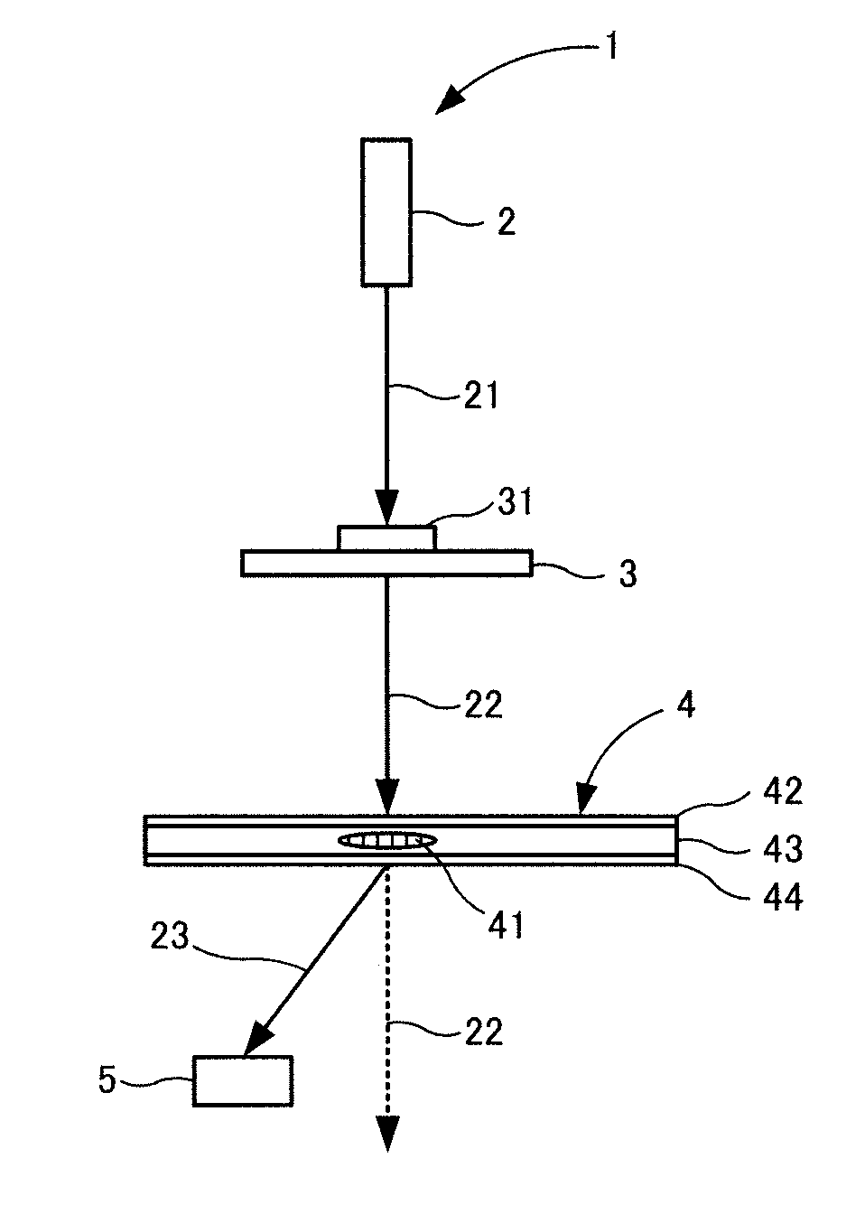
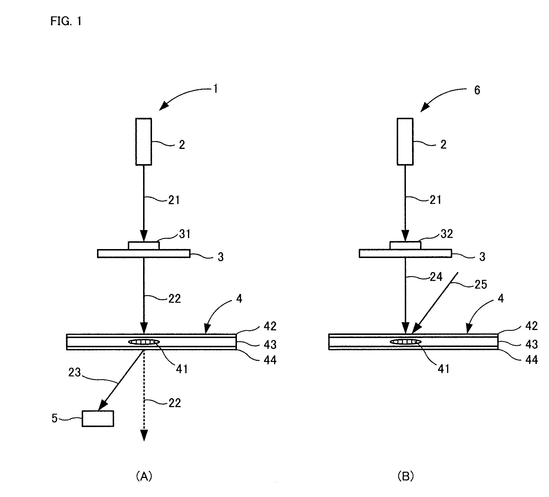
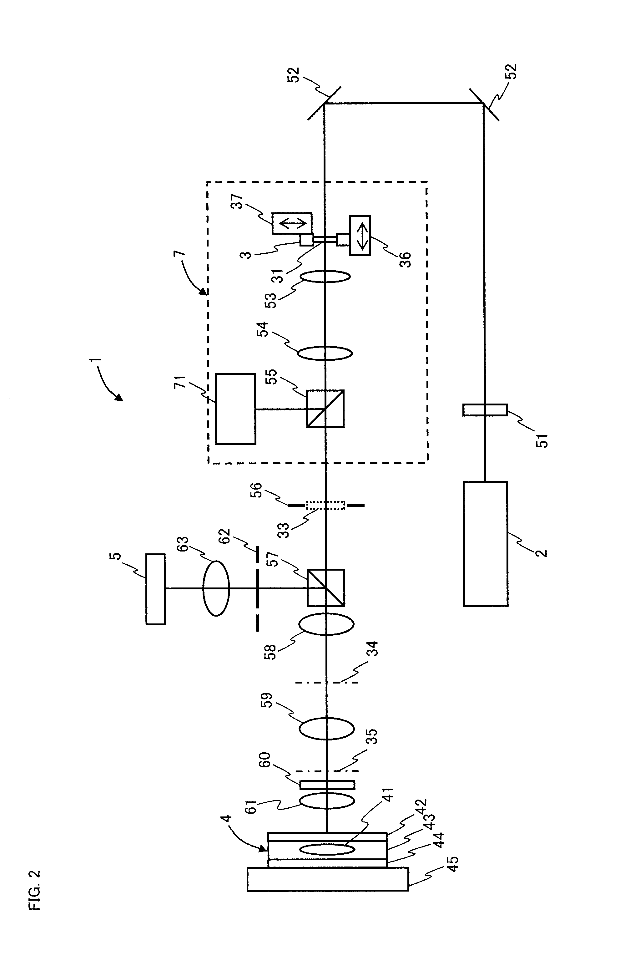
[0088]The device 80 in FIG. 6 was used to demonstrate the possibility of identifying phase objects. In this example, a Nd:YVO4 laser of 532 nm was used as the light source 81. As the mask 89, masks in the shapes shown in FIGS. 3(A) and 3(B) were used. More specifically, the mask for identification was a mask with a circular opening 56a in the center for generating sample light, whereas the mask for recording was a mask with a circular opening 56b in the center for generating object light and with twelve small circular openings 56c around the circular opening 56b in a radial fashion for generating reference light. The openings 56a and 56b for the profile of sample light or object light had a circular shape with a diameter of 1 mm, whereas the openings 56c for generating reference light had a circular shape with a diameter of 0.29 mm. In addition, the objective lens 92 had NA of 0.55 and a focal length of 4 mm.

[0089]First, four types of holograms 41 were recorded on the holographic re...

example 2

[0091]The device 80 in FIG. 6 was used to demonstrate the possibility of identifying phase objects in response to change in phase. The device in this example had the same conditions as in Example 1. First, the phase was changed by π / 4 from 0 to 2π for all of the pixels in the display region of 32×32 pixels of the phase spatial light modulator 84 to generate object light for each pixel, and record nine holograms by interference between the object light and the reference light. More specifically, the object light in accordance with the phase patterns in which the phase was set to 0, π / 4, π / 2, π / 4, π, 5π / 4, 3π / 2, 7π / 4, and 2π for all of the pixels in the display region was used to record holograms 0, π / 4, π / 2, 3π / 4, π, 5π / 4, 3π / 2, 7π / 4, and 2π.

[0092]These nine holograms were irradiated with sample light generated in accordance with a phase pattern in which the phase was set to 0 for all of the pixels in the display region. FIG. 9 shows the results of detecting reproduced light reproduc...


PUM


Abstract

An object of the invention is to provide a phase object identification device and method which can identify a phase object in a completely different manner from conventional methods for observing or measuring a phase object.A phase object identification device 1 for identifying a phase object for changing the phase of light includes a light source 2, a sample holding means 3 for holding a phase object 31 to be identified, a holographic recording medium 4 on which a hologram 41 formed by interference between reference light 25 and object light 24 that is phase-modulated by a known phase object 32 is recorded, and a light detector 5, a phase of light 21 emitted from the light source is modulated by the phase object to be identified to generate sample light 22, the hologram of the holographic recording medium is irradiated with the sample light, reproduced light 23 reproduced from the hologram of the holographic recording medium is detected by the light detector.

Description

TECHNICAL FIELD[0001]The present invention relates to a phase object identification device and a method for identifying an object (hereinafter, referred to as a “phase object”) for changing the phase of light, more particularly, relates to a phase object identification device and a method for identifying a phase object to be identified with the use of holography, and also relates to novel applications using the phase object identification device and the method.BACKGROUND ART[0002]While the simplest approach for observing an object is an observation by the naked eye, the naked eye is intended to detect the change in light intensity, and thus not suitable for the observation of an object which brings about no change in light intensity or an object which brings about a small change in light intensity. The same applies to common photographs and image sensors because the change in light intensity is detected for the photographs and image sensors. For example, biological cells, bacteria, ...

Claims


Application Information

Patent Timeline
Patent Type & Authority Applications(United States)
IPC IPC(8): G01B9/021
CPCG01J9/02G03H1/041G03H1/0005G03H1/2286G03H2001/0038G03H2001/0066G03H2001/0072G03H2001/0413G03H2001/0428G03H2001/2244G03H2210/11G03H2210/12G03H2223/12G03H2223/13G03H2223/55G01N21/453
Inventor WATANABE, ERIKOKODATE, KASHIKO
Owner JAPAN SCI & TECH CORP
Why Eureka
Try Eureka