Vehicle fuel vapor management

a technology for fuel vapor and vehicles, applied in the direction of condensed fuel collection/return, charge feed system, non-fuel substance addition to fuel, etc., can solve the problems of inability to purge carbon canisters, infrequent engine operation, carbon canister saturation, etc., to reduce or eliminate carbon canister saturation, improve fuel economy, and reduce weight

Inactive Publication Date: 2012-08-21
FORD GLOBAL TECH LLC
View PDF26 Cites 14 Cited by
  • Summary
  • Abstract
  • Description
  • Claims
  • Application Information

AI Technical Summary

Benefits of technology

[0018]Embodiments of the present disclosure provide various advantages. For example, evaporative emissions management according to the present disclosure reduces or eliminates carbon canister saturation due to the diurnal expansion / contraction cycles. Furthermore, if the carbon canister becomes saturated, the gases in the fuel vapor recovery system are contained within the bladder to accommodate changes in system volume due to diurnal temperature increases / decreases. Embodiments of the present disclosure facilitate use of a plastic fuel tank, which may contribute to reduced weight and improved fuel economy. Similarly, use of a light-weight, collapsible bladder rather than increasing the volume of the carbon canister may: reduce overall vehicle weight, improve fuel economy, and aid in underhood packaging.

Problems solved by technology

A problem encountered in some modern vehicles is that the engine is operated infrequently at a condition which is favorable for purging the carbon canister.
During such operation, the carbon canister cannot be purged without otherwise unnecessary operation of the internal combustion engine.
Consequently, there are also concerns with fully purging the carbon canisters coupled to these engines.
Additionally, any engine employing measures to reduce pumping losses, such as using variable valve timing (VVT), lean burn, stratified charge, homogeneous-charge compression-ignition (HCCI), etc., also encounters difficulty in having sufficient operation at high manifold vacuums to purge the carbon canister as desired.
When a canister becomes saturated, no additional fuel vapors can be stripped from gases passing through the carbon canister and any fuel filling or expansion of gases in the fuel tank due to temperature changes would result in displaced gases which contain fuel vapors being unintentionally released to the atmosphere.
A particularly troublesome situation occurs when a vehicle is parked for multiple days.
After a number of such cycles, the carbon canister may become saturated and successive cycling may result in release of fuel vapors.
Such a system requires more costly components: steel fuel tank (compared to plastic tanks commonly used), stronger construction of the carbon canister, and fittings / connectors throughout the system that seal under both pressure and vacuum.
This is in contrast with prior art systems having no ability to increase the system volume.
The bladder has insufficient capacity to hold the gases displaced from fuel tank filling.

Method used


Image

  • Vehicle fuel vapor management
  • Vehicle fuel vapor management
  • Vehicle fuel vapor management

Examples


Embodiment Construction

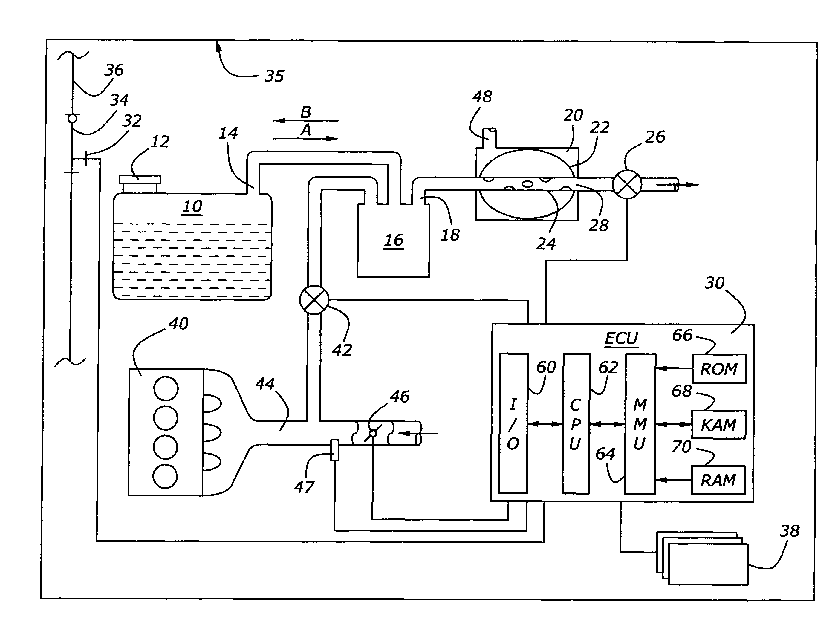
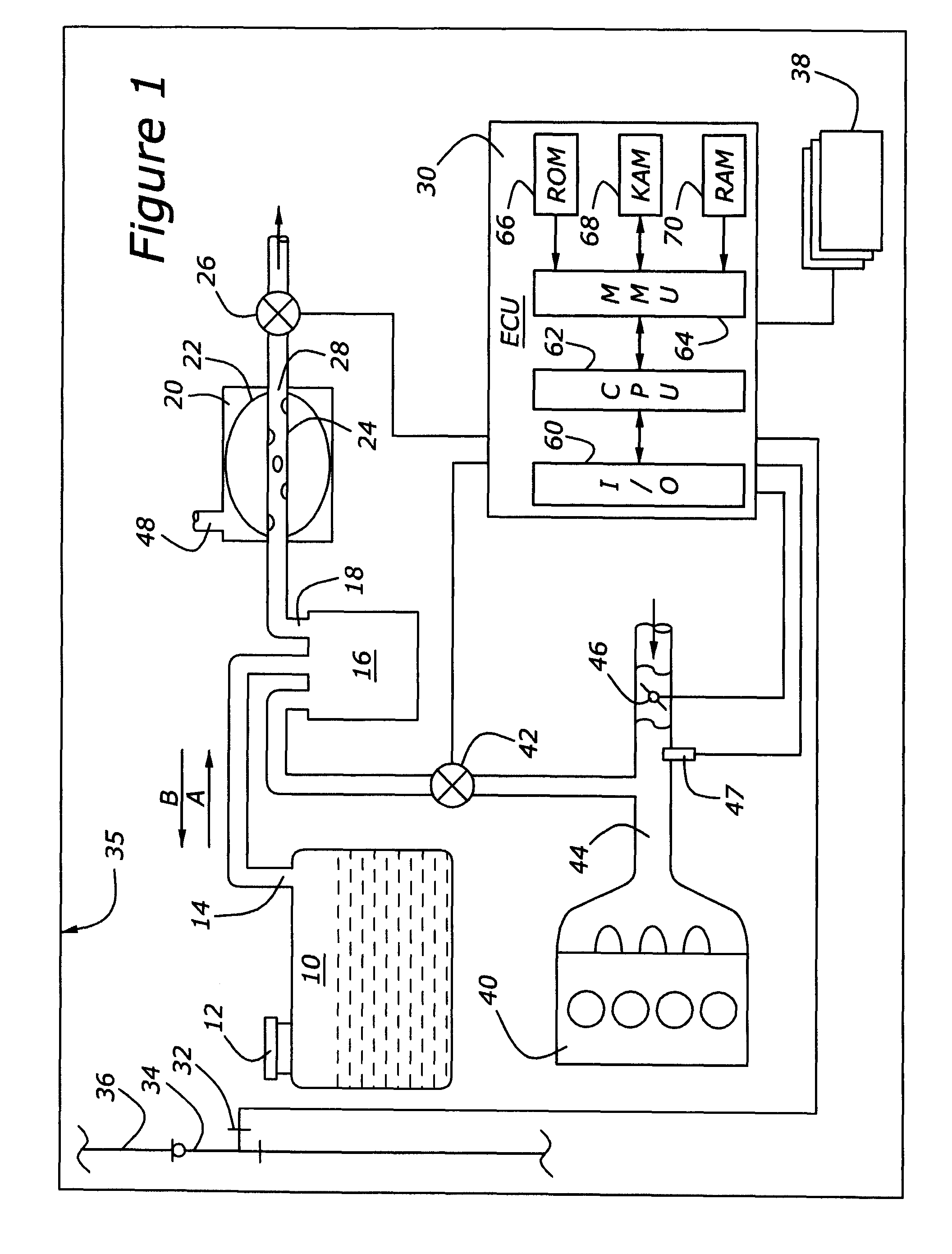
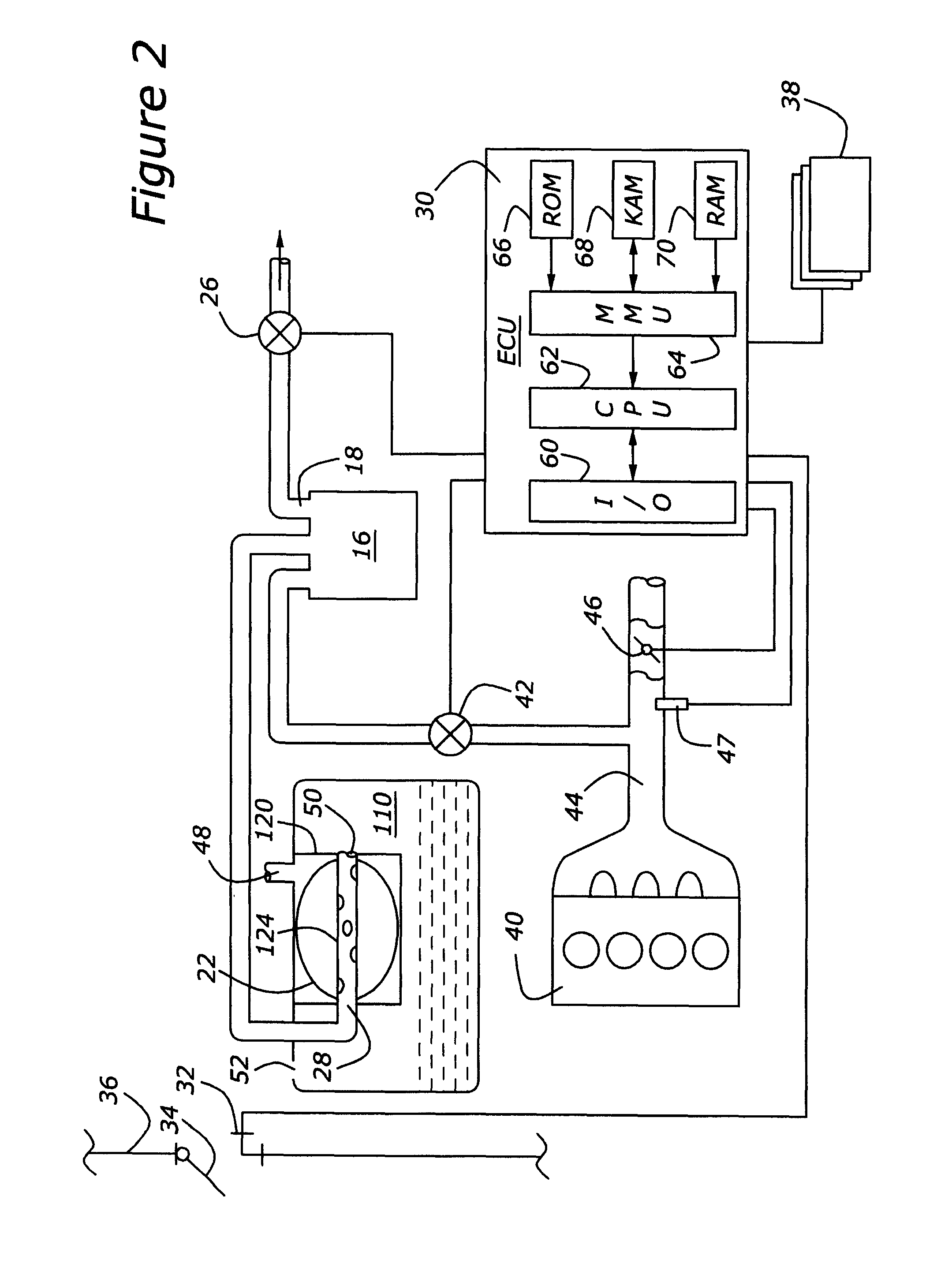
[0022]As those of ordinary skill in the art will understand, various features of the embodiments illustrated and described with reference to any one of the Figures may be combined with features illustrated in one or more other Figures to produce alternative embodiments that are not explicitly illustrated or described. The combinations of features illustrated provide representative embodiments for typical applications. However, various combinations and modifications of the features consistent with the teachings of the present disclosure may be desired for particular applications or implementations. The representative embodiments used in the illustrations relate generally to a vapor recovery system for a vehicle equipped with a gasoline fueled engine. Those of ordinary skill in the art may recognize similar applications or implementations consistent with the present disclosure for other use in turbocharged, hybrid electric, plug-in hybrid electric, direct injection, stratified charge,...


PUM


Abstract

A fuel vapor recovery system and method for an automotive vehicle are disclosed. The vehicle fuel tank is vented to atmosphere via a passageway having a carbon canister to remove fuel vapors, a bladder, and a normally-closed isolation valve. When fueling the vehicle, the gases in the fuel tank displaced by entering fuel are introduced into the carbon canister where the fuel vapors are stored. The isolation valve is commanded to open to allow such flow through the carbon canister. When the vehicle is parked for a period of a day, it undergoes a diurnal temperature change which causes fuel to vaporize into the fuel system. According to an aspect of the present development, the isolation valve remains closed and the gases are contained within the bladder as it expands or contracts as the volume of gases increases or decreases in response to temperature changes.

Description

BACKGROUND[0001]1. Technical Field[0002]The present development relates to management of fuel evaporative emissions.[0003]2. Background Art[0004]A typical automobile has a carbon canister coupled to a vent of the fuel tank. Activated carbon pellets in the carbon canister strip fuel vapors from the gases displaced by fuel entering the fuel tank during a refueling operation. The gases that have been stripped of fuel are vented out of the carbon canister to the atmosphere. Additionally, due to natural daily temperature changes (diurnal cycle) to which the vehicle is subjected when parked, the fuel is heated and cooled, thereby vaporizing and condensing fuel, respectively. If the vehicle fuel and fuel tank temperatures increase by 30° F., the volume of the gases above the fuel in the fuel tank expands by about 25 liters for a typical automotive fuel tank. By having a vent from the fuel tank into the carbon canister, fuel vapors from the gases expanding out of the fuel tank are adsorbed ...

Claims


Application Information

Patent Timeline
Patent Type & Authority Patents(United States)
IPC IPC(8): F02M33/02
CPCF02M25/0872
Inventor PETERS, MARKHOFFMAN, STEVEN JAMESHEDGES, JOHN
Owner FORD GLOBAL TECH LLC
Why Eureka
Try Eureka