
Method and device for producing metal foils

a metal foil and foil technology, applied in the direction of crystal growth process, basic electric elements, electrical equipment, etc., can solve the problem of unsuitable feedback

Active Publication Date: 2012-08-21
RGS DEVMENT
View PDF5 Cites 2 Cited by
  • Summary
  • Abstract
  • Description
  • Claims
  • Application Information

AI Technical Summary

Benefits of technology

[0007]It is an object of the present invention to enable the thickness of the metal foils to be controlled more successfully during the production process than has been possible with known methods.

Problems solved by technology

Hitherto, feedback of this nature has not been deemed appropriate, since it has been assumed that the process does not react sufficiently to a change in the processing parameters used, such as the temperature of the substrate.

Method used


Image

  • Method and device for producing metal foils
  • Method and device for producing metal foils
  • Method and device for producing metal foils

Examples


Embodiment Construction

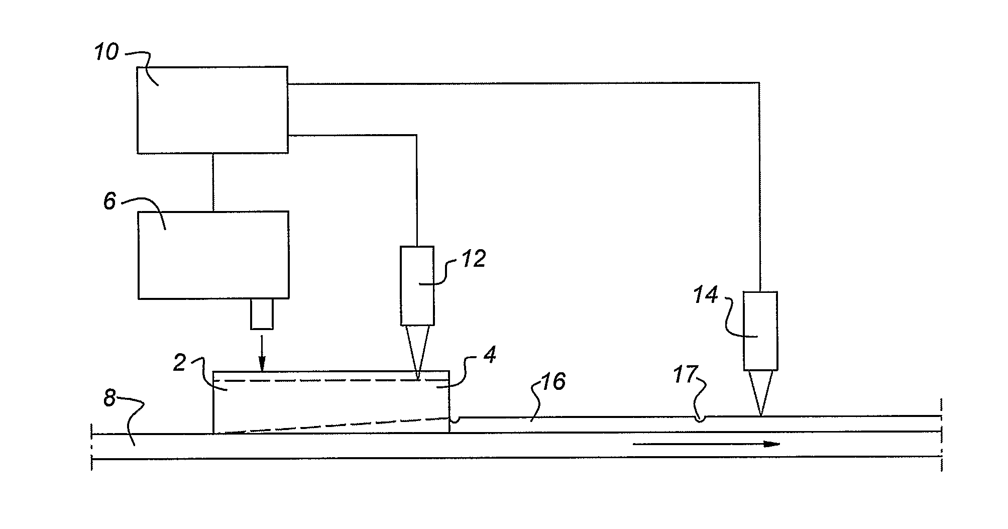
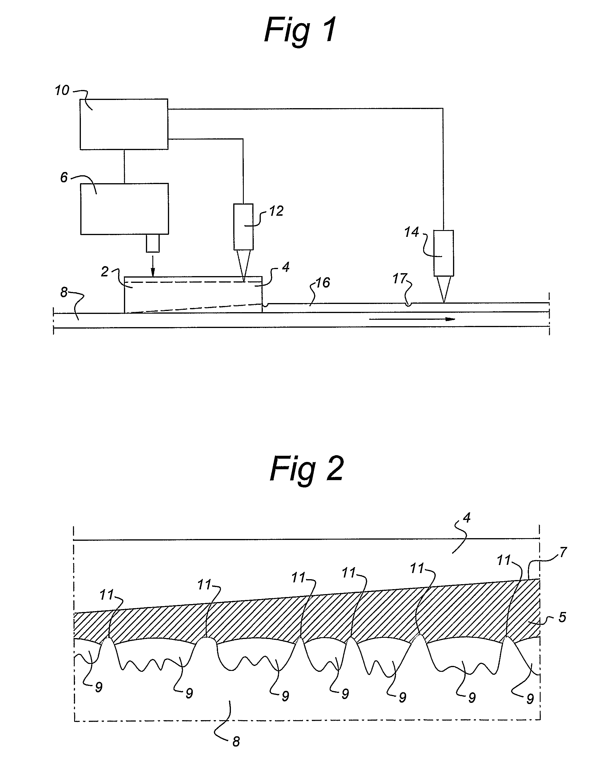
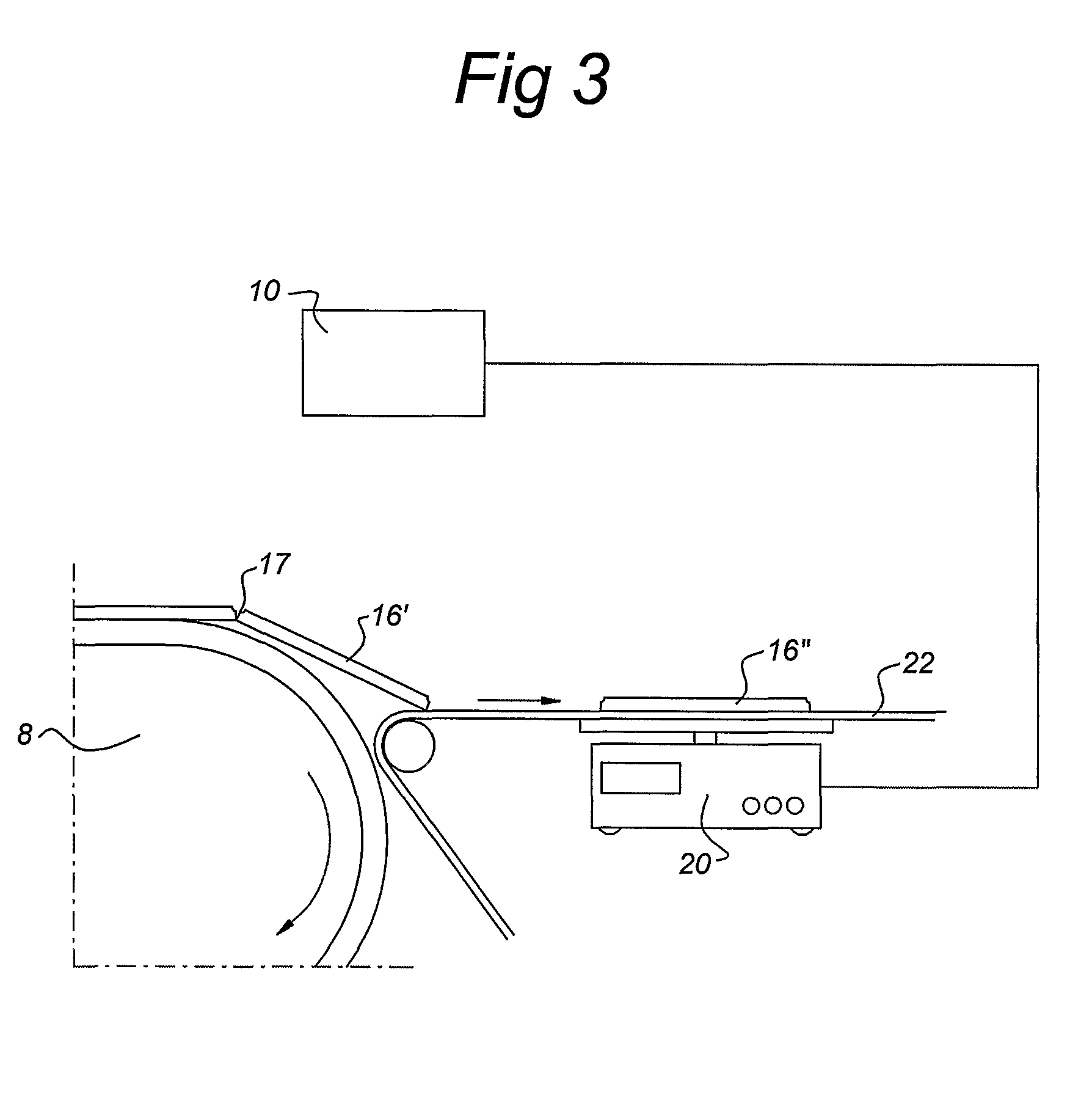
[0019]FIG. 1 shows a diagrammatic side view of a foil casting device in accordance with one embodiment of the present invention. The device for producing metal foils comprises a casting frame 2, into which a liquid metal can be poured. The liquid metal 4 is poured into the casting frame 2 with the aid of a feed device 6. Beneath the casting frame 2 there is a substrate belt 8 which is designed to move through the bottom of the casting frame 2 at a set speed. The drive device required for this purpose is not shown in FIG. 1. Furthermore, the foil-casting device comprises a control module 10 and a level meter 12 designed to determine the level of the liquid metal 4 in the casting frame 2. The temperature of the substrate belt 8 is set to be such that the liquid metal 4 crystallizes at the surface of the substrate belt 8. Since the substrate belt 8 is moving, to the right in FIG. 1, a foil 16 will be formed at a downstream side of the casting frame 2. This foil 16 presses the casting f...


PUM

PropertyMeasurementUnit
surface roughnessaaaaaaaaaa
temperatureaaaaaaaaaa

Abstract

A method and device for producing metal foils using the foil-casting principle includes the steps of filling a casting frame with liquid metal, moving a substrate through the bottom of the casting frame, with the substrate belt being at a lower temperature than the melting point of the liquid metal in the bottom of the casting frame, so that a bottom layer of the liquid metal crystallizes on the substrate and a metal foil is formed on the substrate on one side of the casting frame. The method further includes the steps of measuring at least one of a thickness and weight of the metal foil, and adjusting the contact surface area between the liquid metal and the substrate as a function of the measured value for the thickness and / or weight of the foils produced.

Description

BACKGROUND OF THE INVENTION[0001]1. Field of the Invention[0002]The invention relates to a method for producing metal foils by the foil-casting principle, comprising the steps of:[0003]filling a casting frame with liquid metal;[0004]moving a substrate through the bottom of the casting frame, the substrate being at a lower temperature than the melting point of the liquid metal, so that a bottom layer of the liquid metal crystallizes on the substrate, and a metal foil is formed on the substrate on one side of the casting frame.[0005]2. Description of the Related Art[0006]DE 100 47 929 A1 describes a method in which the level of the liquid metal in the casting frame is measured with the aid of a float. If the level is too high, the pressure in the bottom of the casting frame can become so high that liquid metal escapes beneath the walls of the casting frame. As a result, lumps can form on the top surface of the foils, which has a significant adverse affect on the quality of the foils. ...

Claims


Application Information

Patent Timeline
Patent Type & Authority Patents(United States)
IPC IPC(8): C30B19/08C30B15/00H01L31/18
CPCC30B15/007H01L31/18C30B15/00
Inventor SCHONECKER, AXEL GEORGSTEINBACH, KARL INGO
Owner RGS DEVMENT
Learn More