Segmented ceramic matrix composite turbine airfoil component

a composite turbine and ceramic matrix technology, applied in the direction of machines/engines, stators, liquid fuel engines, etc., can solve the problems of high stress on blades, high heat on turbine blades and vanes, and inconvenient production of thick cmc material parts

Active Publication Date: 2012-08-28
RTX CORP
View PDF27 Cites 55 Cited by
  • Summary
  • Abstract
  • Description
  • Claims
  • Application Information

AI Technical Summary

Problems solved by technology

During operation of the engine, the turbine blades and vanes are subjected to high heat from the gas.
Additionally, the blades are subjected to high stresses from rotational forces.
It is, therefore, a constant design challenge to develop materials for turbine blades and vanes that are more heat resistant to reduce cooling demands, and lighter to increase propulsive efficiencies in aircraft engines.
Production of thick CMC material parts is constrained because of manufacturing limitations in infusing the liquid matrix into deep layering of the preformed fabric.
Furthermore, due to the two-dimensional nature of the ceramic fabric, difficulties arise in producing parts having complex three-dimensional shapes.
For example, it is difficult to produce CMC material turbine blades having both a radially extending airfoil component and an axially extending platform component.
However, previous attempts at producing CMC material components have resulted in complex designs that limit the benefits of using CMC material in turbine blades.
Such a vane design is impractical for turbine blades because the stack extends radially in the direction in which severe stresses are generated within a rotating turbine blade.
Furthermore, the mechanical tensioning means typically comprises threaded fasteners fabricated from an alloy that requires cooling, thus limiting the temperature benefits of using CMC material in a hot section of a gas turbine engine.

Method used


Image

  • Segmented ceramic matrix composite turbine airfoil component
  • Segmented ceramic matrix composite turbine airfoil component
  • Segmented ceramic matrix composite turbine airfoil component

Examples


Embodiment Construction

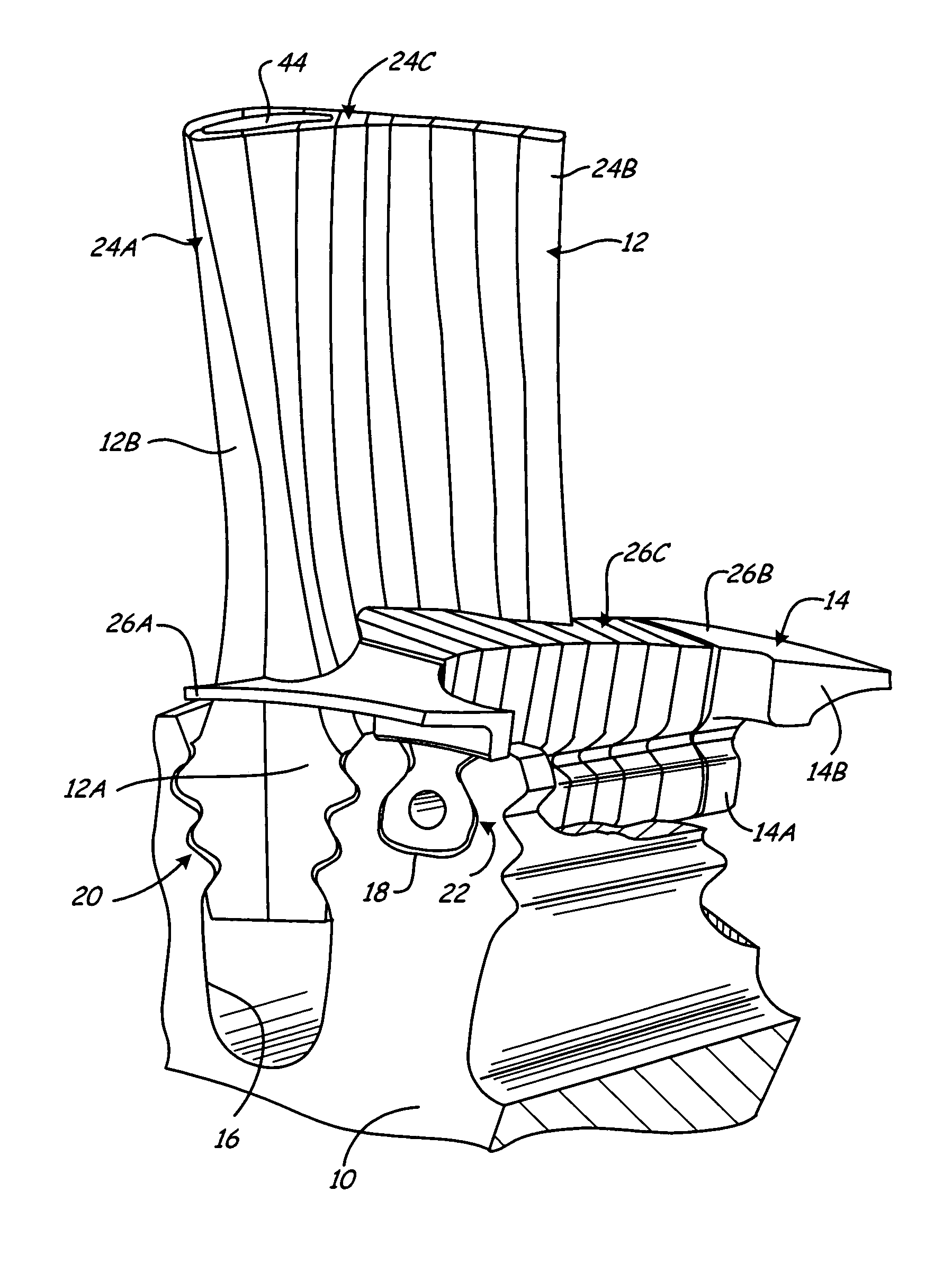
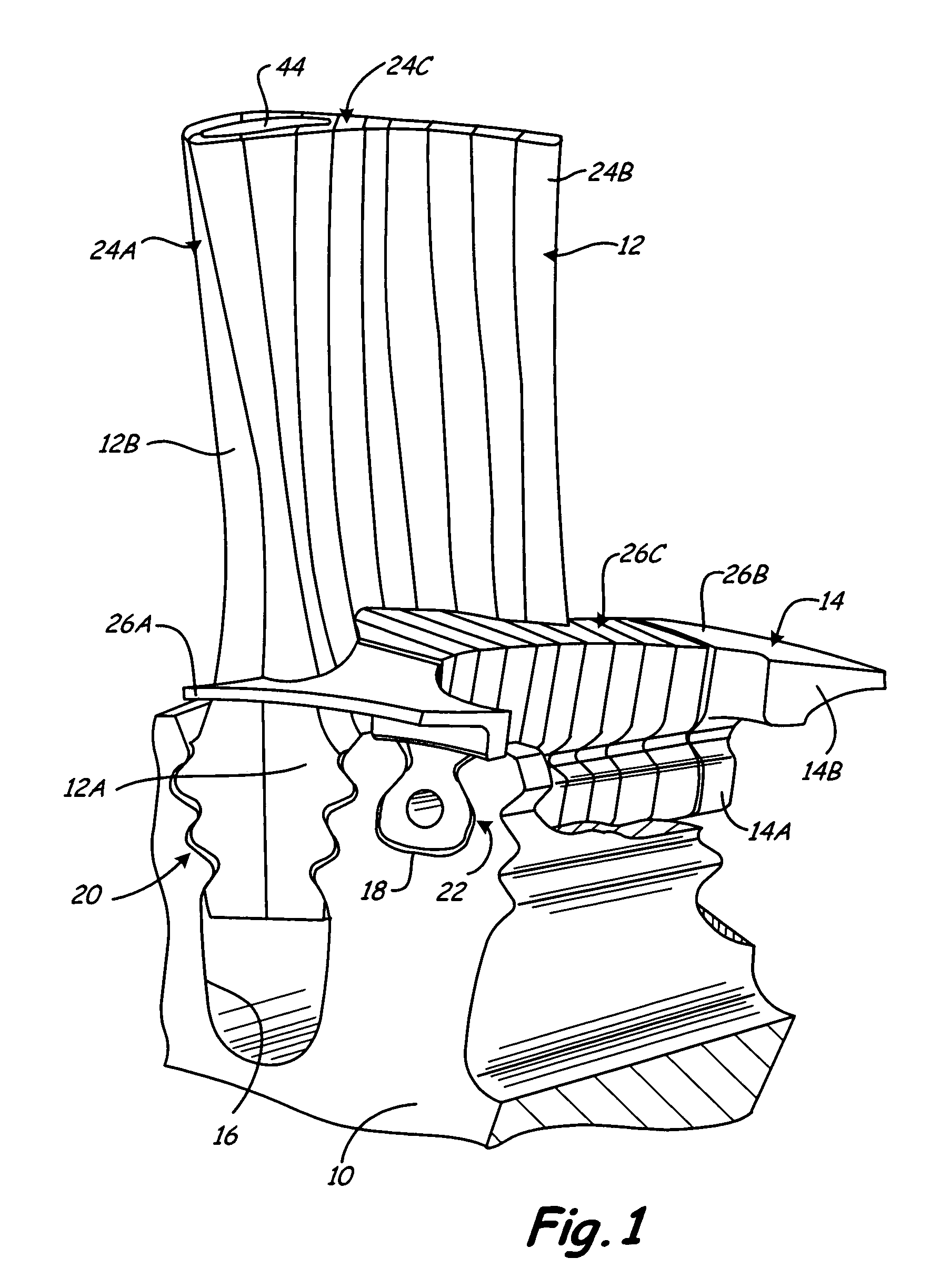
[0017]FIG. 1 shows a cut-away perspective view of rotor 10 connected to segmented ceramic matrix composite (CMC) material rotor blade components 12 and 14 of the present invention. Rotor 10 comprises an annular body, such as a disk, that is configured to rotate about an axial centerline within a gas turbine engine. Rotor 10 includes an inner diameter configured to be connected to a shaft in a gas turbine engine in any conventional manner, and an outer diameter configured to connect to segmented CMC blade 12 and segmented CMC platform 14 at retention slots 16 and 18, respectively. Blade 12 and platform 14 each include a root portion and a gas path portion. Specifically, blade 12 includes blade root 12A, which is connected to slot 16, and airfoil 12B. Likewise, platform 14 includes platform root 14A, which is connected to slot 18, and stage 14B. Blade 12 and platform 14 comprise one cluster of a plurality of clusters that would typically be disposed about the outer periphery of rotor ...


PUM


Abstract

A segmented component for use with a gas turbine engine comprises a radially extending gas path portion. The gas path portion is for interacting with gas flow from the gas turbine engine. The component is divided into axially aligned segments comprising a forward segment, an aft segment, and a plurality of middle segments disposed between the forward segment and the aft segment. The middle segments comprise radially elongate ceramic matrix composite material plates. In one embodiment, the gas path portion comprises an airfoil for a turbine blade. In another embodiment, the gas path portion comprises a removable platform for a turbine blade. In another embodiment, the gas path portion comprises an airfoil for a turbine vane.

Description

BACKGROUND[0001]The present invention is directed to airfoil components for gas turbine engines and, more particularly, to ceramic matrix composite turbine blades, vanes and platforms.[0002]Gas turbine engines comprise one or more rotating turbines that are used to extract energy from a high velocity and high temperature gas flow produced within the gas turbine engine. The turbines are comprised of a plurality of radially extending airfoil blades that are connected at their inner diameter ends to a rotor, which is connected to a shaft that rotates within the engine as the blades interact with the gas flow. The rotor typically comprises a disk having a plurality of axial retention slots that receive mating root portions of the blades to prevent radial dislodgment. Blades typically also include integral inner diameter platforms that prevent the high temperature gases from escaping through the radial retention slots. Between the turbine blades are disposed a plurality of radially exten...

Claims


Application Information

Patent Timeline
Patent Type & Authority Patents(United States)
IPC IPC(8): F01D9/02
CPCF01D5/284F01D5/3015Y02T50/672Y02T50/673F05D2240/80Y02T50/60
Inventor PROPHETER-HINCKLEY, TRACY A.SHI, JUN
Owner RTX CORP
Why Eureka
Try Eureka