
Phase lock loop with phase interpolation by reference clock and method for the same

a reference clock and phase lock technology, applied in the direction of phase difference detection, automatic control of pulses, angle demodulation, etc., can solve the problems of degrading the output clock of the pll, ring oscillators are very noisy in general,

Active Publication Date: 2012-08-28
REALTEK SEMICON CORP
View PDF13 Cites 126 Cited by
  • Summary
  • Abstract
  • Description
  • Claims
  • Application Information

AI Technical Summary

Benefits of technology

The patent describes a phase lock loop (PLL) that uses phase interpolation to control the phase of an output clock. The PLL includes a phase-interpolation controller, a phase / frequency detector, a loop filter, a phase-interpolated oscillator, and a divide-by-N circuit. The method involves generating a phase-interpolation control signal, detecting the phase difference between a reference clock and a feedback clock, filtering the phase error signal to generate a control signal, generating an output clock under the control of the control signal and the phase interpolation control signal, and dividing down the output clock by a factor of N to generate the feedback clock. The technical effect of this invention is to provide a more accurate and efficient way to control the phase of an output clock.

Problems solved by technology

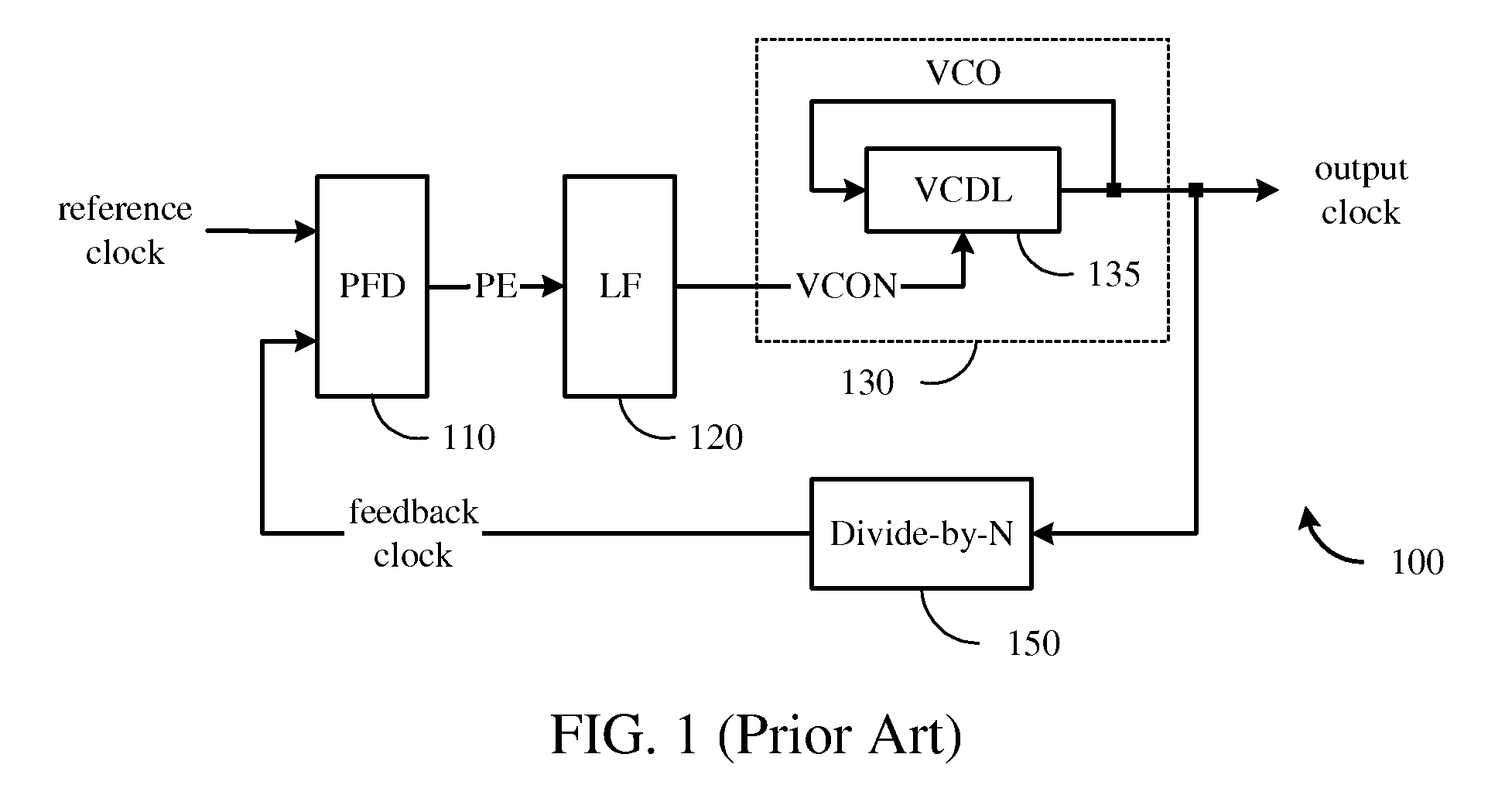
It has been well known that a ring oscillator is very noisy in general, due to the noise accumulation as the oscillating clock circulates through the VCDL 135 over and over.
The noise in the ring oscillator degrades the quality of the output clock of the PLL.

Method used


Image

  • Phase lock loop with phase interpolation by reference clock and method for the same
  • Phase lock loop with phase interpolation by reference clock and method for the same
  • Phase lock loop with phase interpolation by reference clock and method for the same

Examples


Embodiment Construction

[0015]While the specifications described several example embodiments of the invention considered best modes of practicing the invention, it should be understood that the invention can be implemented in many ways and is not limited to the particular examples described below or to the particular manner in which any features of such examples are implemented. In other instances, well-known details are not shown or described to avoid obscuring aspects of the invention.

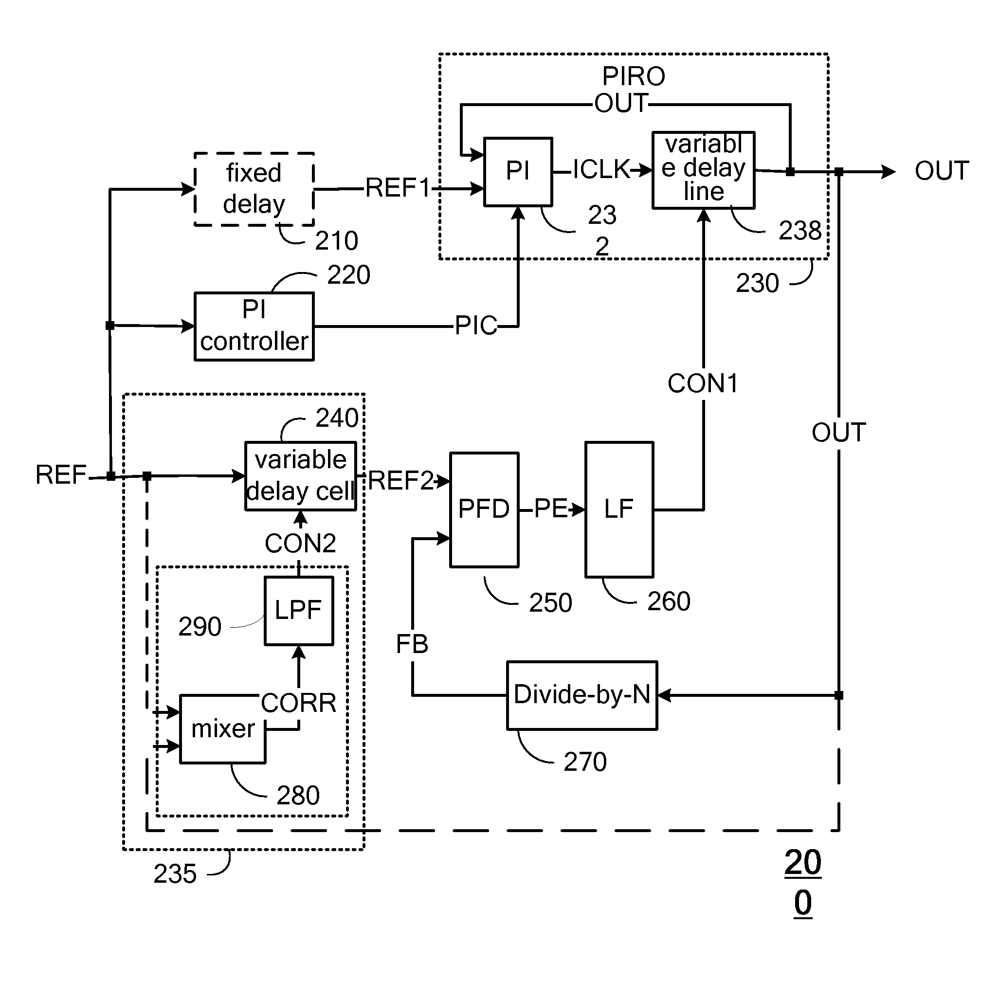
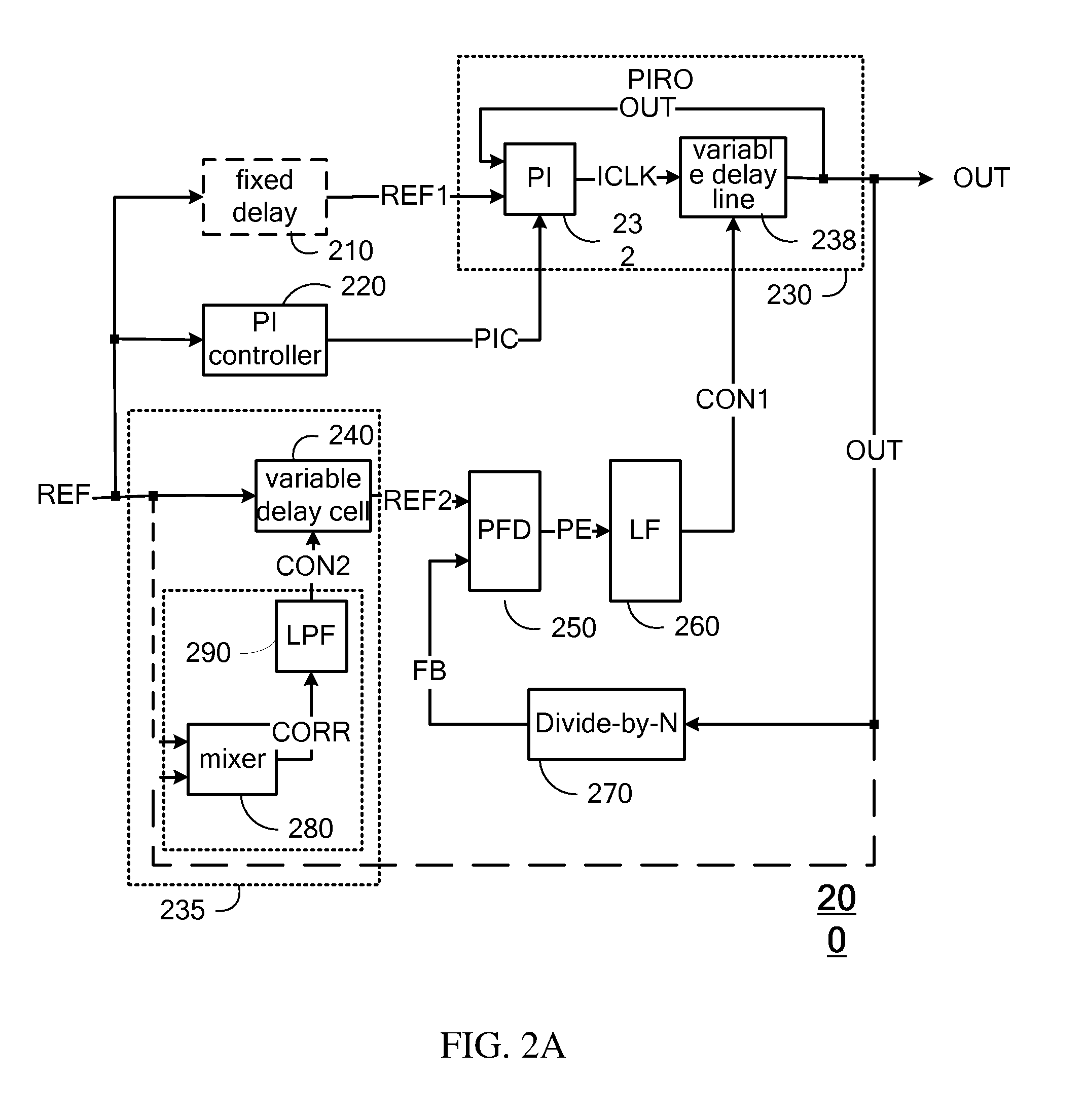
[0016]As mentioned earlier, a ring oscillator is very noisy in general, due to the noise accumulation as the oscillating clock circulates through the delay line over and over. The noise in the ring oscillator degrades the quality of the PLL output clock. In comparison, a reference clock is usually a much less noisy clock. One may improve the quality of the PLL output clock by phase interpolating the oscillating clock using the reference clock. Also, care must be taken to make the phase interpolation seamless without introdu...


PUM


Abstract

The present invention relates to a PLL that utilizes a phase interpolation by a reference clock. The PLL includes a phase-interpolated controller for generating a phase-interpolation control signal; a phase / frequency detector for detecting a phase difference between a second reference clock and a feedback clock and outputting a phase error signal to represent the phase difference; a loop filter for filtering the phase error signal to generate a first control signal; a phase-interpolated oscillator for generating an output clock under a control by the phase-interpolation control signal and the first control signal; and a divide-by-N circuit for dividing down the output clock by a factor of N to generate the feedback clock, where N is an integer.

Description

CROSS REFERENCE TO RELATED APPLICATIONS[0001]This application claims the benefit of U.S. Provisional Application No. 61 / 015,670, filed on Dec. 21, 2007 and entitled “PHASE LOCK LOOP WITH PHASE INTERPOLATION BY REFERENCE CLOCK AND METHOD FOR THE SAME”, the contents of which are incorporated herein by reference.BACKGROUND OF THE INVENTION[0002]1. Field of the Invention[0003]The present invention relates to phase lock loop (PLL), in particular to PLL that employs phase interpolation by reference clock.[0004]2. Description of Related Art[0005]Phase lock loop (PLL) is an important circuit for numerous applications. FIG. 1 depicts a typical PLL 100 for receiving a reference clock and generating an output clock that is phase locked to the reference clock but has an N times higher frequency, where N is an integer. PLL 100 comprises: a phase / frequency detector (PFD) 110 for detecting a phase difference between the reference clock and a feedback clock and generating a phase error signal PE to...

Claims


Application Information

Patent Timeline
Patent Type & Authority Patents(United States)
IPC IPC(8): H03L7/06
CPCH03L7/07H03L7/0812H03L7/0998H03L2207/06H03L7/0814
Inventor LIN, CHIA-LIANG
Owner REALTEK SEMICON CORP
Learn More