
Method and device for inspecting a traveling wire cable

a technology of traveling wire and inspection method, which is applied in the direction of transportation and packaging, instruments, and elevators, etc., can solve the problems of complicated, inability to carry out in practice, and inability to test magnetoinductive wires on traveling cables

Inactive Publication Date: 2012-08-28
CASAR DRAHTSEILWERK SAAR GMBH
View PDF7 Cites 8 Cited by
  • Summary
  • Abstract
  • Description
  • Claims
  • Application Information

AI Technical Summary

Benefits of technology

[0005]It is the object of the invention to make available a further, simple method for inspecting a traveling wire cable.
[0018]Consequently, the correct instant for the next picture or flash illumination is respectively ensured in a simple way, even when there is a change in the time intervals when starting up or braking the wire cable, or for other reasons such as certain changes in lay length over the length of a hanging cable.
[0027]The length of the wire cable detected in the image need not be limited to a lay length or said multiple of the lay length. If it is larger, a fault can simply appear twice in the image. This need not, however, result in irritation, but can even lead to enhancing the perception.

Problems solved by technology

This cannot be carried out in practice.
Magnetoinductive wire cable testing on traveling cables is possible, but complicated.

Method used


Image

  • Method and device for inspecting a traveling wire cable
  • Method and device for inspecting a traveling wire cable
  • Method and device for inspecting a traveling wire cable

Examples


Embodiment Construction

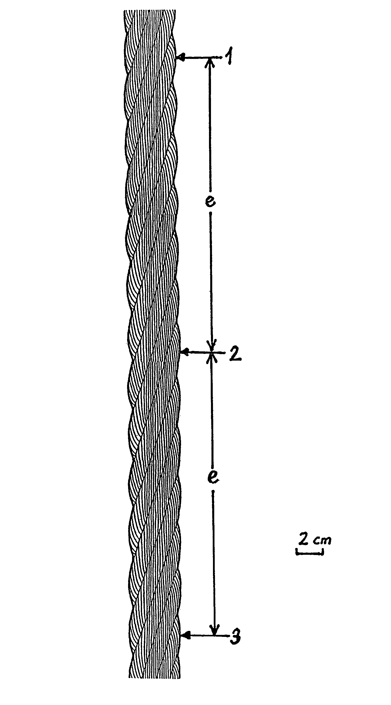
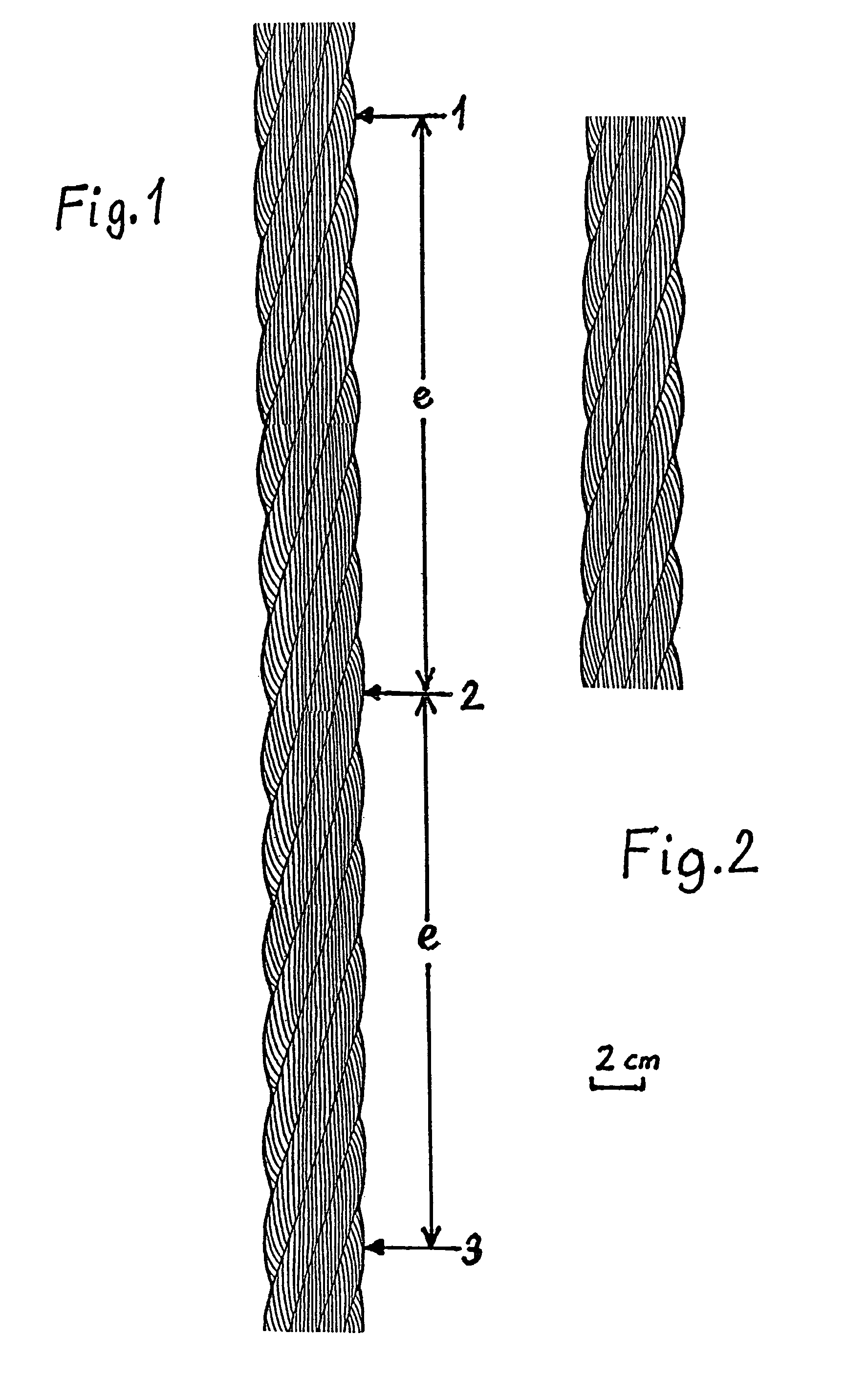
[0044]In FIG. 1, the arrows 1, 2 and 3 point to the successive occurrence of the same strand at the same 25 position, offset in each case by the lay length e, of the cable circumference of a wire cable 10. The same strands in the same configuration are visible between the arrows 1 and 2 and between the arrows 2 and 3.

[0045]This configuration is illustrated per se in FIG. 2.

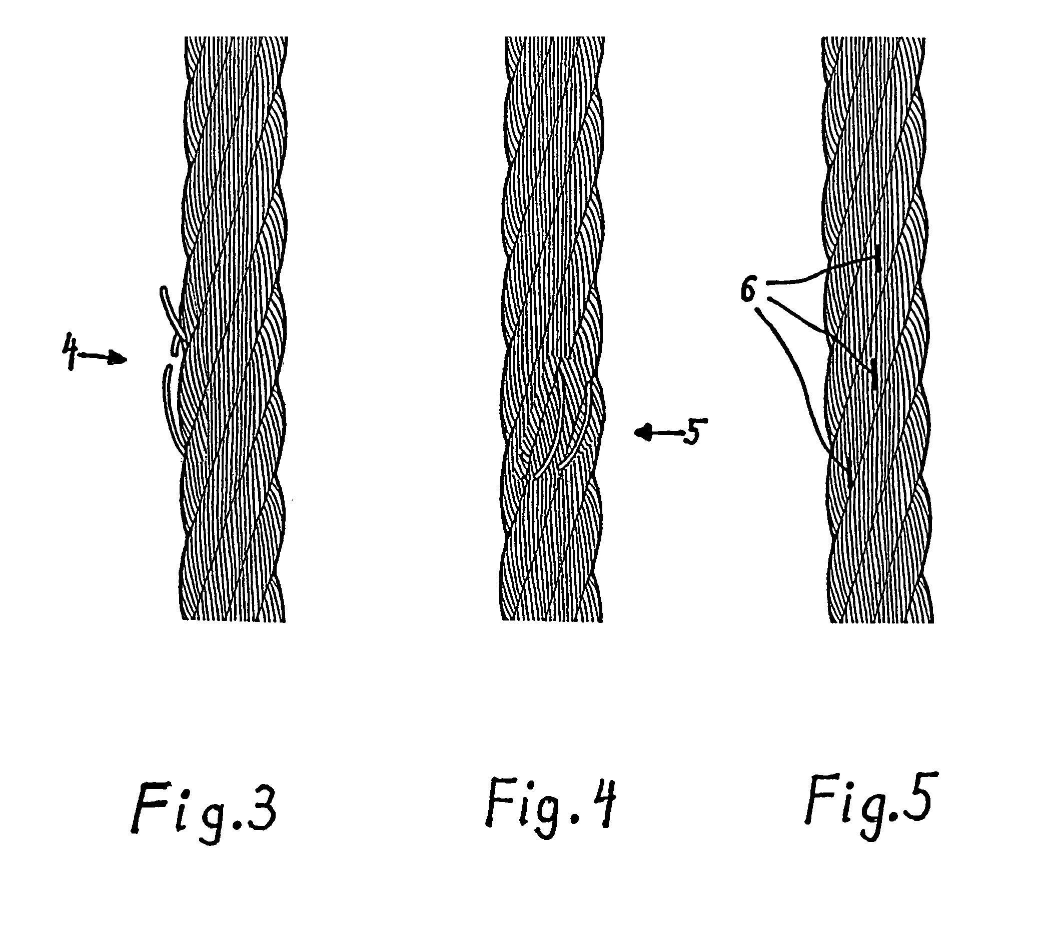
[0046]It is respectively illustrated once again in FIGS. 3, 4 and 5, there with wire breaks 4 and 5 and 6, respectively. The wire breaks 4 and 5 are illustrated exaggeratedly. At the wire breaks 6, the wire has merely retracted somewhat and left a gap that has filled with dirt and lubricant and is to be recognized as a short dark line.

[0047]FIG. 6 shows a station with three camera 7 directed onto the wire cable 10 from various sides. Lines 8 mark the regions acquired by the cameras 7.

[0048]The lay length of the strands 9 of the wire cable 10 is 250 mm in the present example, the travel speed of the wire cable 10 p...


PUM


Abstract

In a first embodiment, a picture is taken of the traveling wire cable in a stationary position at intervals that are equal to the ratio produced from the lay length or a multiple of the lay length and the travel speed of the wire cable, at least op one lay length or the above-mentioned multiple of the lay length, and the successive images are compared on at least one lay length or the above-mentioned multiple of the lay length and are monitored for changes in the image which are indicative of damages. In a second embodiment, the wire cable is instead of taking pictures exposed to flashes and the exposed image is detected on at least one lay length or the above-mentioned multiple of the lay length and monitored for changes in the image. Preferably, the respective repetition of the same outer stranded wire of the traveling wire cable is detected in the same location and every repetition or every other repetition or every third repetition is used for triggering the taking of a picture or for triggering the flash. In a third embodiment, a picture is taken of a large portion of the wire cable using a specialized camera and the image is split up into recurring units of length that correspond to the size of a lay length or a multiple of the lay length and the successive units of length are compared and inspected for changes in the image.

Description

BACKGROUND OF THE INVENTION[0001]The invention relates to a method for inspecting a traveling wire cable.[0002]It further relates to a device for carrying out the method.[0003]Wire cables per se are to be examined visually on a daily basis for wire breaks and the occurrence of other faults. This cannot be carried out in practice. In order to be examined, the wire cable must be stationary or travel very slowly, and the work must be interrupted.[0004]Magnetoinductive wire cable testing on traveling cables is possible, but complicated.SUMMARY OF THE INVENTION[0005]It is the object of the invention to make available a further, simple method for inspecting a traveling wire cable.[0006]In accordance with the invention, it is provided in a first version that the traveling wire cable is photographed at a stationary position at time intervals that are equal to the quotient of the lay length or a multiple of the lay length, and the travel speed of the wire cable, at least on one lay length or...

Claims


Application Information

Patent Timeline
Patent Type & Authority Patents(United States)
IPC IPC(8): G06K9/00
CPCB66B7/1238D01H13/26G01N21/8803G01N21/952G01N33/365G01N21/89G01N21/88D06H3/08
Inventor VERREET, ROLAND
Owner CASAR DRAHTSEILWERK SAAR GMBH
Learn More