Light-emitting diode module with a reflecting portion having two inclined planes opposite to each other

a technology of light-emitting diodes and reflecting portions, which is applied in the direction of planar/plate-like light guides, lighting and heating apparatuses, instruments, etc., can solve the problems of non-uniform light sources generated by prior structures with light-emitting diodes, inconvenient manufacturing process, etc., and achieve the effect of increasing the size of light sources and increasing the light sour

Inactive Publication Date: 2012-09-04
LITE ON ELECTRONICS (GUANGZHOU) LTD +1
View PDF3 Cites 24 Cited by
  • Summary
  • Abstract
  • Description
  • Claims
  • Application Information

AI Technical Summary

Benefits of technology

[0006]In view of the aforementioned issues, the present invention provides a light-emitting diode that includes a transparent base and a support. The base has a cavity and a reflecting portion disposed on two opposite sides thereof in order to increase light source. In addition, the size of light source can be increased by increasing the number of the cavity.
[0008]Therefore, the present invention can arrange the light-emitting chips to form a line or surface light source of any sizes by adjusting the numbers of the cavity and the light-emitting chips.

Problems solved by technology

However, the manufacturing process is inconvenient and wastes a lot of time.
In addition, light source generated by prior structure with the light-emitting diodes are non-uniform due to hot spot as shown in FIG. 1.

Method used


Image

  • Light-emitting diode module with a reflecting portion having two inclined planes opposite to each other
  • Light-emitting diode module with a reflecting portion having two inclined planes opposite to each other
  • Light-emitting diode module with a reflecting portion having two inclined planes opposite to each other

Examples


Embodiment Construction

[0022]In the following detailed description of the present invention, the similar elements use the same label.

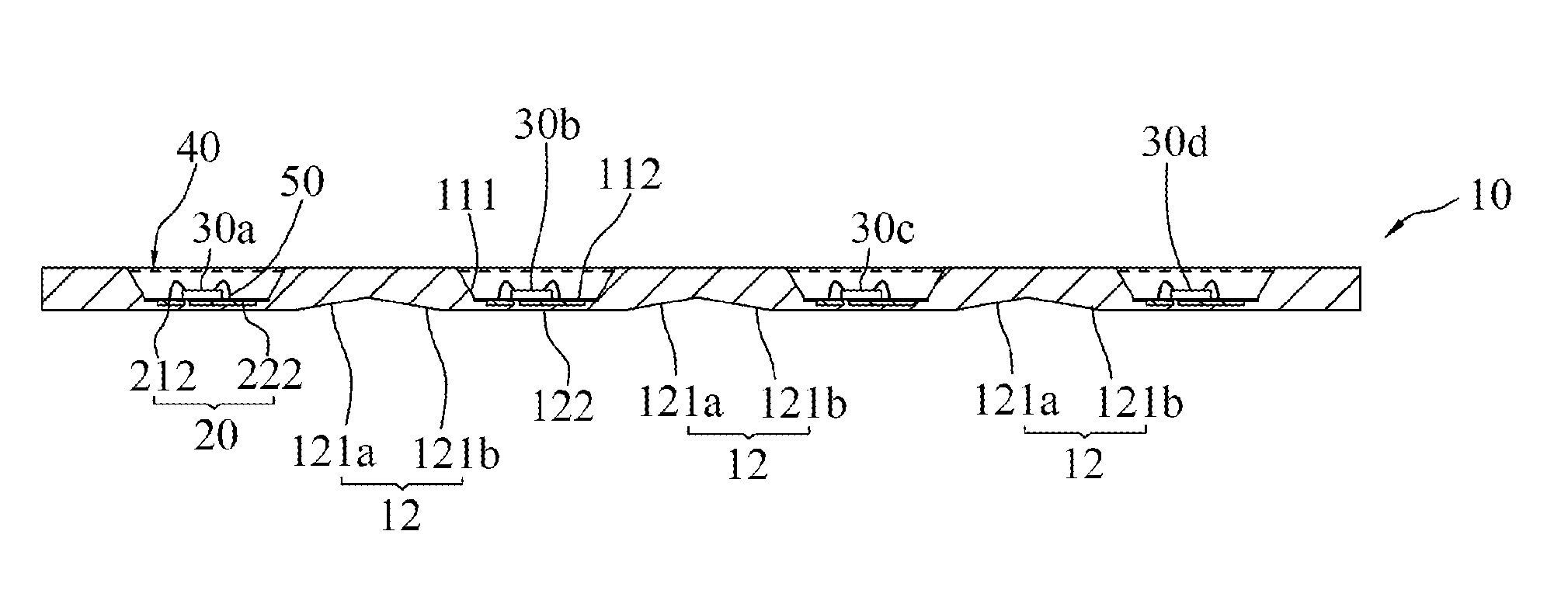
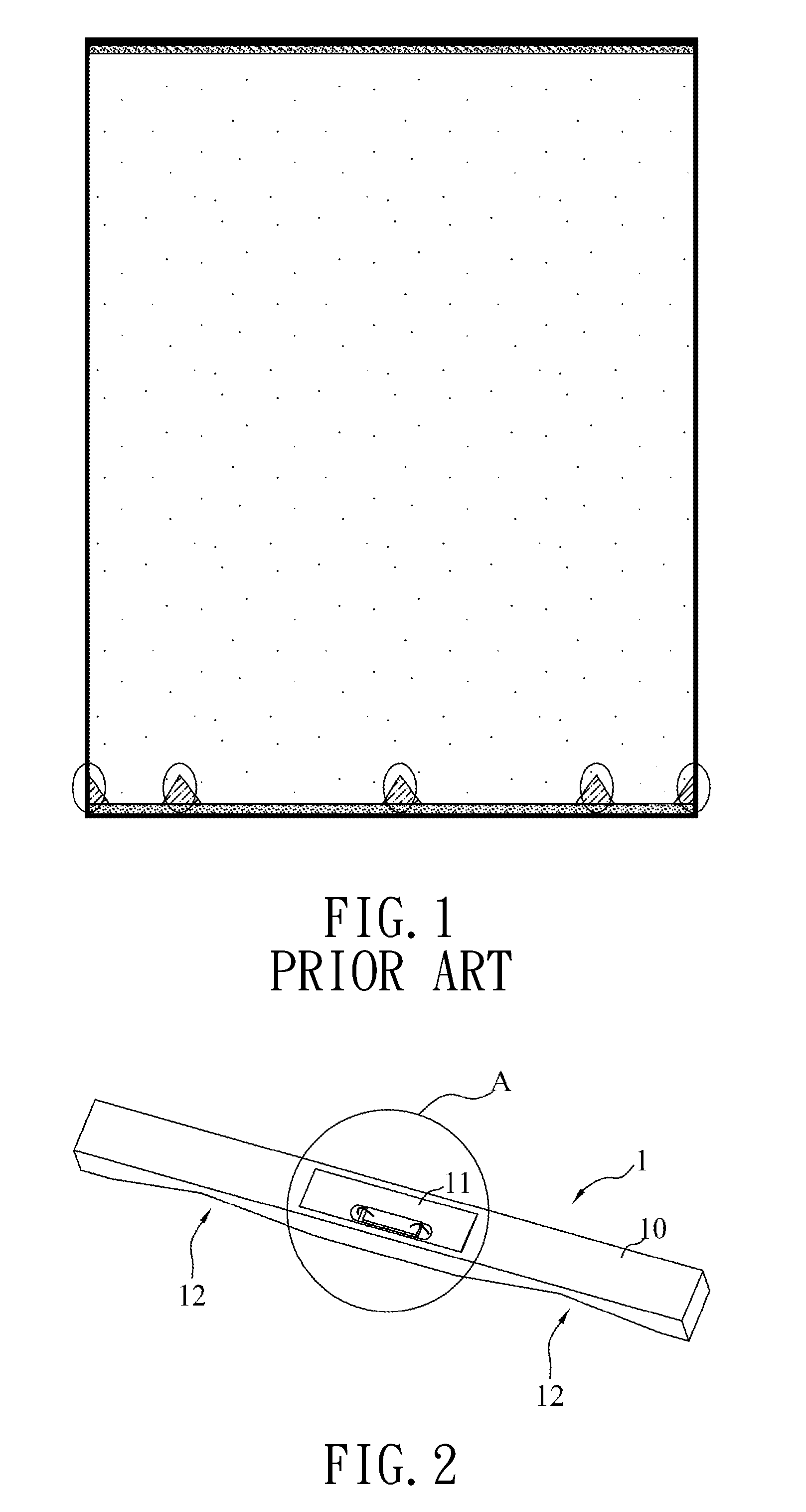
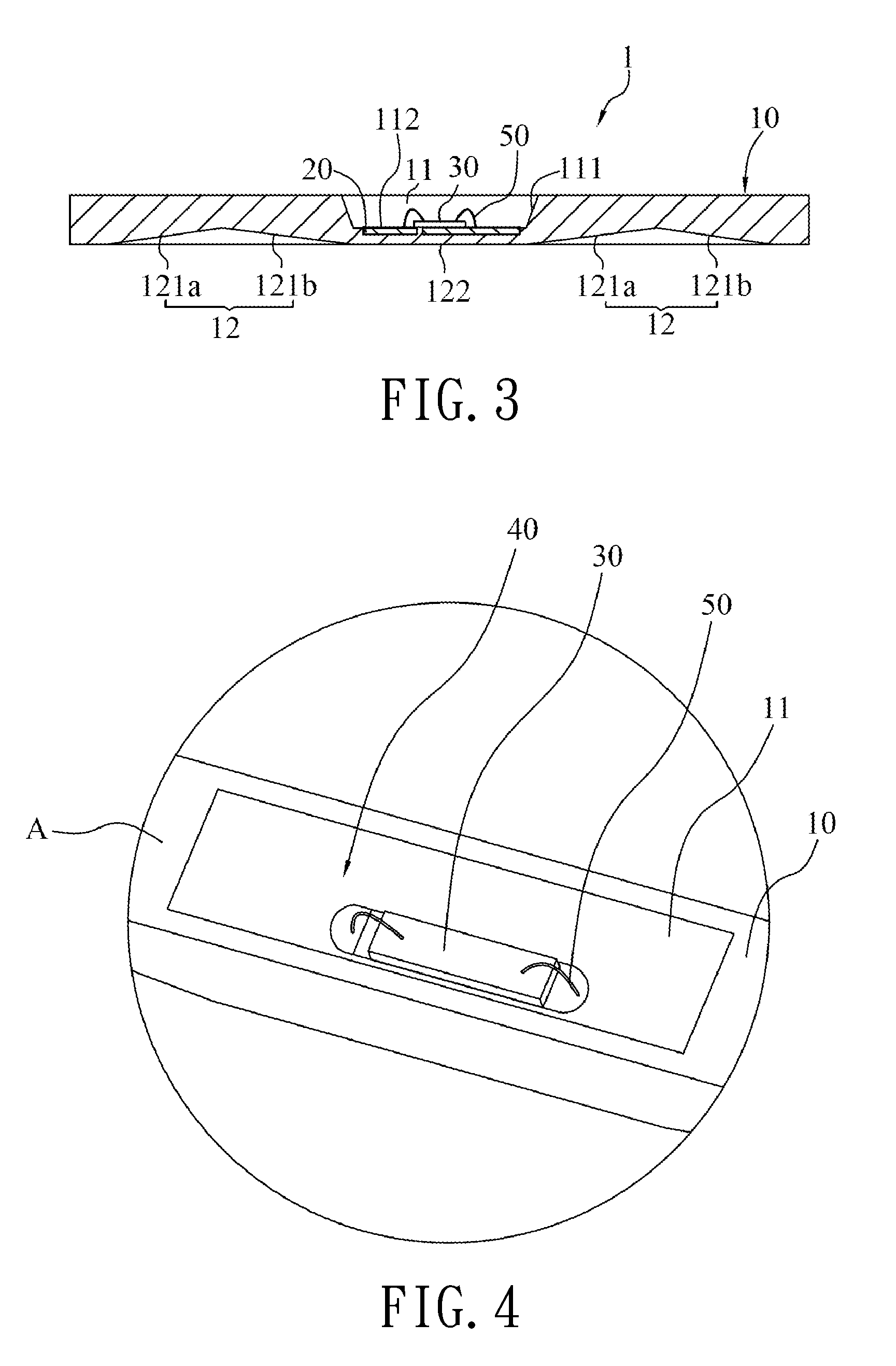
[0023]Referring to FIGS. 2 to 4, one of the best embodiments of the present invention provides an LED (Light-emitting diode) 1, including a support 20, a light-emitting chip 30, a base 10 and a translucent resin 40 combined with the base 10 for packaging the light-emitting chip 30.

[0024]The base 10 is made of transparent material and is a strip shape structure. The base 10 has a cavity 11 formed on the first side (such as top surface) thereof. The shape of the cavity 11 is similar as a funnel that has a width gradually reduced from top to bottom. The cavity 11 has an annular wall 111 and a plane bottom portion 112. The base 10 has a plurality of reflecting portions 12 formed on the second side (such as bottom surface) opposite to the first side which the cavity 11 disposed on. Each of the reflecting portions 12 is composed of at least one inclined plane, such as 121a and 121...


PUM


Abstract

A light-emitting diode module includes a transparent base, a support and a plurality of light-emitting chips. The base has a plurality of cavities separated from each other by a predetermined distance in order to respectively receive the light-emitting chips to form light-exiting areas. The base has a reflecting portion opposite to the cavities. The reflecting portion is at least one inclined plane for reflecting light that have projected outside walls of the cavities to the peripheral area of the light-emitting areas in order to increase the uniformity of the light source. In addition, the light-emitting chips are arranged to form a line or surface light source of any sizes by adjusting the numbers of the cavity and the light-emitting chips.

Description

BACKGROUND OF THE INVENTION[0001]1. Field of the Invention[0002]The present invention relates to a light-emitting diode, in particular, to a light-emitting diode and a module thereof using cavity and inclined plane that are disposed on two opposite sides of a base in order to increase light-emitting efficiency.[0003]2. Description of Related Art[0004]In the prior art, many light-emitting diodes are electrically arranged on a PCB by reflow soldering or wave soldering in order to generate surface light source or apply to product that requires light source. However, the manufacturing process is inconvenient and wastes a lot of time.[0005]Moreover, the optic property and the usage life of the light-emitting diodes would be decreased by heat during reflow soldering or wave soldering process. In addition, light source generated by prior structure with the light-emitting diodes are non-uniform due to hot spot as shown in FIG. 1.SUMMARY OF THE INVENTION[0006]In view of the aforementioned is...

Claims


Application Information

Patent Timeline
Patent Type & Authority Patents(United States)
IPC IPC(8): F21V9/00
CPCG02B6/0031G02B6/009G02B6/0091H01L33/486H01L2224/48091H01L33/60H01L2924/00014
Inventor CHENG, SHUN-CHUNGWANG, HSIU-TSULIANG, CHIH-LUNGWU, CHIA-HAO
Owner LITE ON ELECTRONICS (GUANGZHOU) LTD
Why Eureka
Try Eureka