
Method for reflection time shift matching a first and a second set of seismic reflection data

a technology of reflection data and time shift, applied in the field of reflection time shift matching a, can solve the problems of inability to tolerate new seismic events, forcing the displacement of other seismic events in the seismic data time set in an inappropriate way,

Active Publication Date: 2012-09-04
DEN NORSKE STATS OLJESELSKAP AS
View PDF8 Cites 4 Cited by
  • Summary
  • Abstract
  • Description
  • Claims
  • Application Information

AI Technical Summary

Benefits of technology

The present invention provides a method for calculating time shifts to detect material changes in petroleum bearing strata during petroleum production activities. The method involves acquiring seismic reflection data sets at different times and calculating the reflection time shifts by matching the second set of data with the first set. The method also includes calculating basis function estimates of the time shifts to reduce the calculation effort. The main advantage of the method is that it improves the process of matching seismic data sets and allows for better identification of new seismic events. The calculation of time shifts may be done using spline functions, such as b-splines, which allow for local changes without affecting the global seismic reflection time.

Problems solved by technology

Seismic events that have no significant counterpart may incur the method trying to move a seismic event comprised by a group of samples, say, a new seismic horizon in one of the seismic data time sets, to better fit a seismic event actually not occurring in another seismic data time set, and thus forcing the displacement of other seismic events in the seismic data time set in an inappropriate way.
Further, background art methods have little tolerance for new seismic events, as the matching process may force non-relevant matching onto the seismic data while locally forcing a displacement of otherwise matching parts of time shifted seismic data.

Method used


Image

  • Method for reflection time shift matching a first and a second set of seismic reflection data
  • Method for reflection time shift matching a first and a second set of seismic reflection data
  • Method for reflection time shift matching a first and a second set of seismic reflection data

Examples


Embodiment Construction

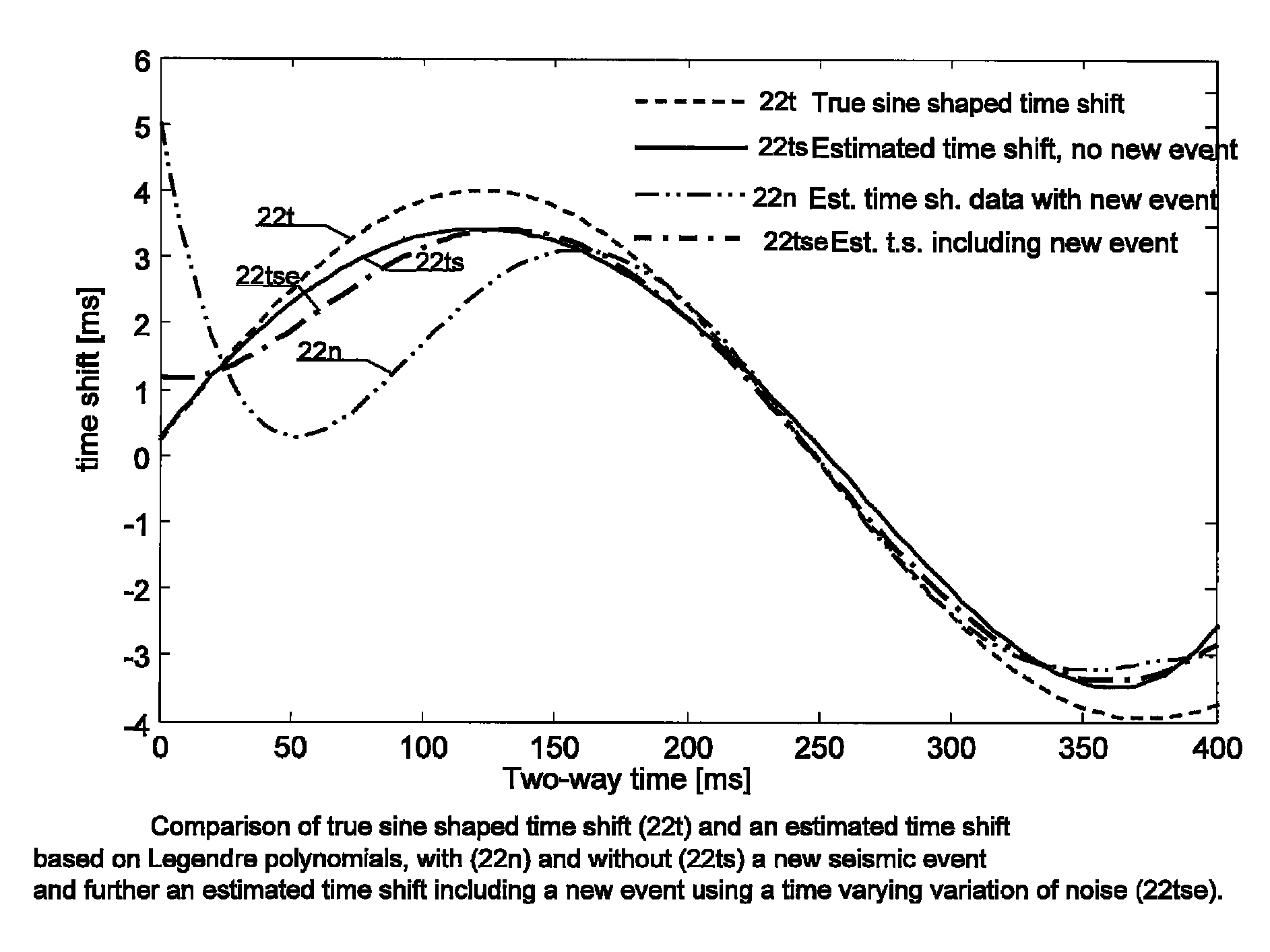
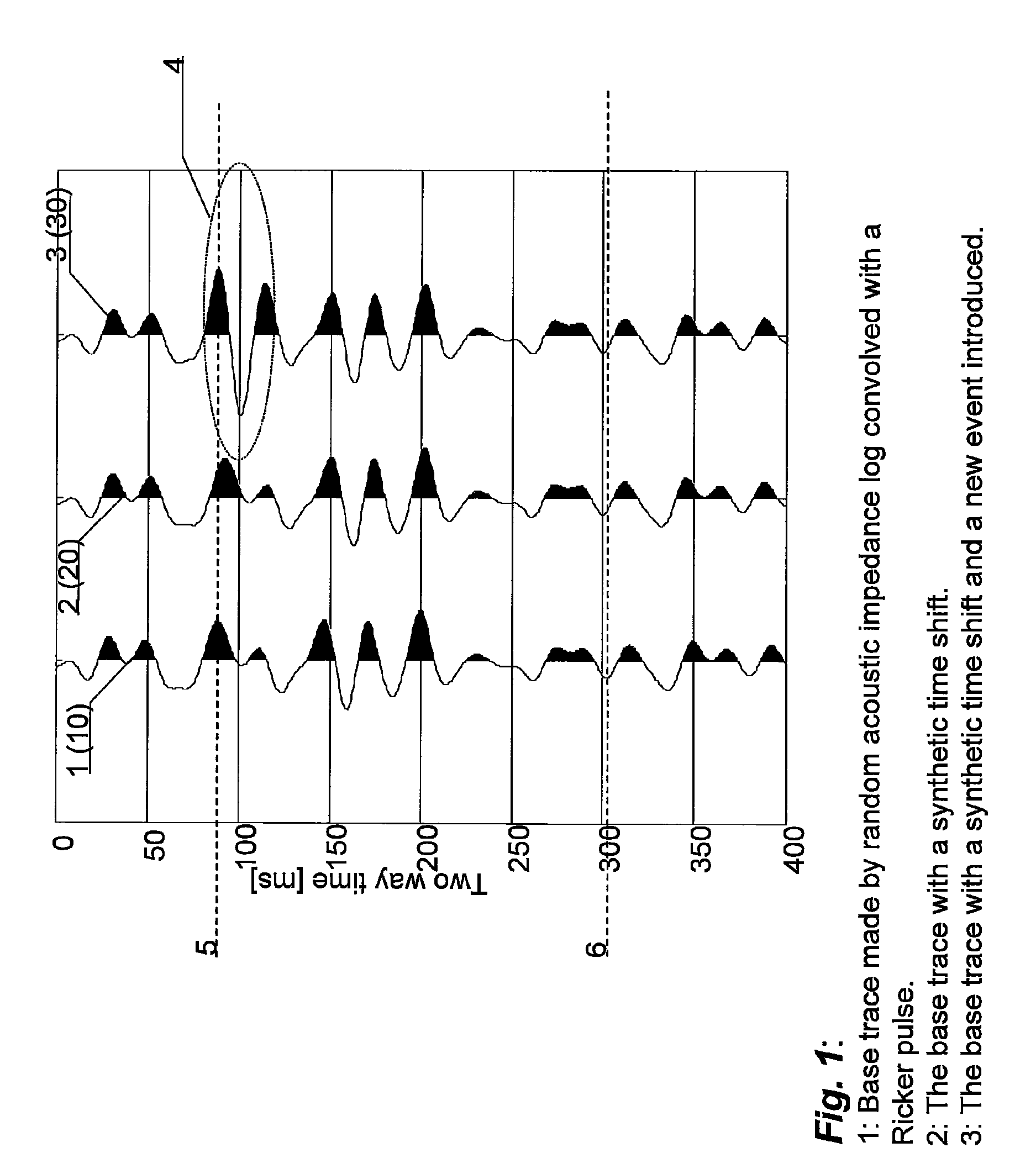
[0035]A base reflection trace 1 is formed by making a random acoustic impedance log of an imagined or real geological column. Each layer's acoustic impedance is the acoustic velocity multiplied by the density. The random impedance log used here has been convolved with a Ricker pulse, and is illustrated by 1 in the left third of FIG. 1. The random reflection trace 1 so produced is imagined to having been acquired at a first time t0. The middle trace indicated by reference numeral 2 is the same randomly made base trace, but given a synthetic time shift, here a sine function time displacement. The time shifted reflection trace 2 is imagined to having been acquired at a second, later time t. (The second time t may also be an earlier time.) One will see from the traces 1,2 that about 0.10 seconds, marked by a time indicator line 5, corresponding ripples occur later in the time shifted trace 2 than for the base trace 1, and about 0.30 s, marked by another time indicator line 6, the pulses...


PUM


Abstract

A method is disclosed for reflection time shift matching a first and a second set of seismic reflection data (10,30) comprising first and second seismic reflection traces (1,3) with series of generally corresponding seismic reflections (11,31). The second set of seismic data (30) comprises at least one laterally extending series (40) of new seismic events (4) not present in the first set of seismic data (10). Reflection time shifts (22) are calculated as required for matching seismic reflections (31) of the second reflection traces (3) of the second seismic reflection data (30) with corresponding seismic reflections (11) of the first reflection traces (1). The calculation of the time shifts (22) are made by calculating coefficients of basis function estimates such as Legendre polynomials in order to save calculation effort.

Description

[0001]This Nonprovisional application claims priority under 35 U.S.C. §119(e) on U.S. Provisional Application No. 61 / 064,866 filed on Mar. 31, 2008, the entire contents of which are hereby incorporated by reference.[0002]The present invention relates to a method for reflection time shift matching a first and a second set of seismic reflection data.[0003]The invention relates generally to correction of time shifts between seismic data sets acquired at different times during the life of a petroleum field. In an embodiment, the invention provides a method for correcting time shifts differences between two seismic data sets under the further constraint that new seismic events occur in the data, the new seismic events possibly having no counterpart in previously measured seismic data sets.BACKGROUND ART[0004]For finding petroleum fluids in geological strata the seismic method is the prime method. Seismic signals are generated at the surface and propagate downward and are partly reflected...

Claims


Application Information

Patent Timeline
Patent Type & Authority Patents(United States)
IPC IPC(8): G01V1/00
CPCG01V1/364
Inventor LIE, ESPEN OEN
Owner DEN NORSKE STATS OLJESELSKAP AS
Learn More