
Occupant detection and imaging system

a technology for imaging systems and occupants, applied in the direction of process and machine control, instruments, pedestrian/occupant safety arrangements, etc., can solve the problems of limited system ability

Inactive Publication Date: 2012-09-04
TOYOTA MOTOR CO LTD
View PDF11 Cites 20 Cited by
  • Summary
  • Abstract
  • Description
  • Claims
  • Application Information

AI Technical Summary

Benefits of technology

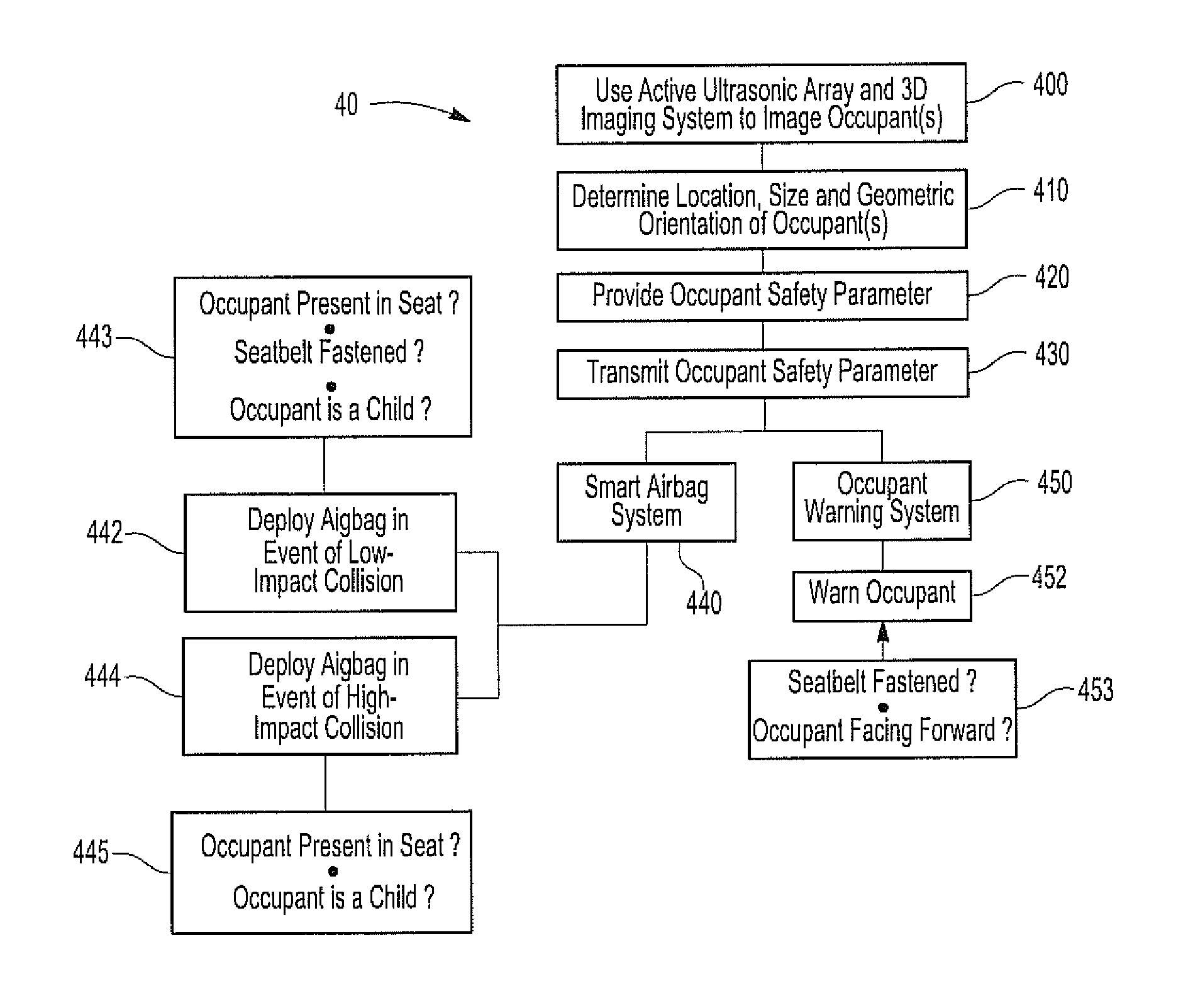
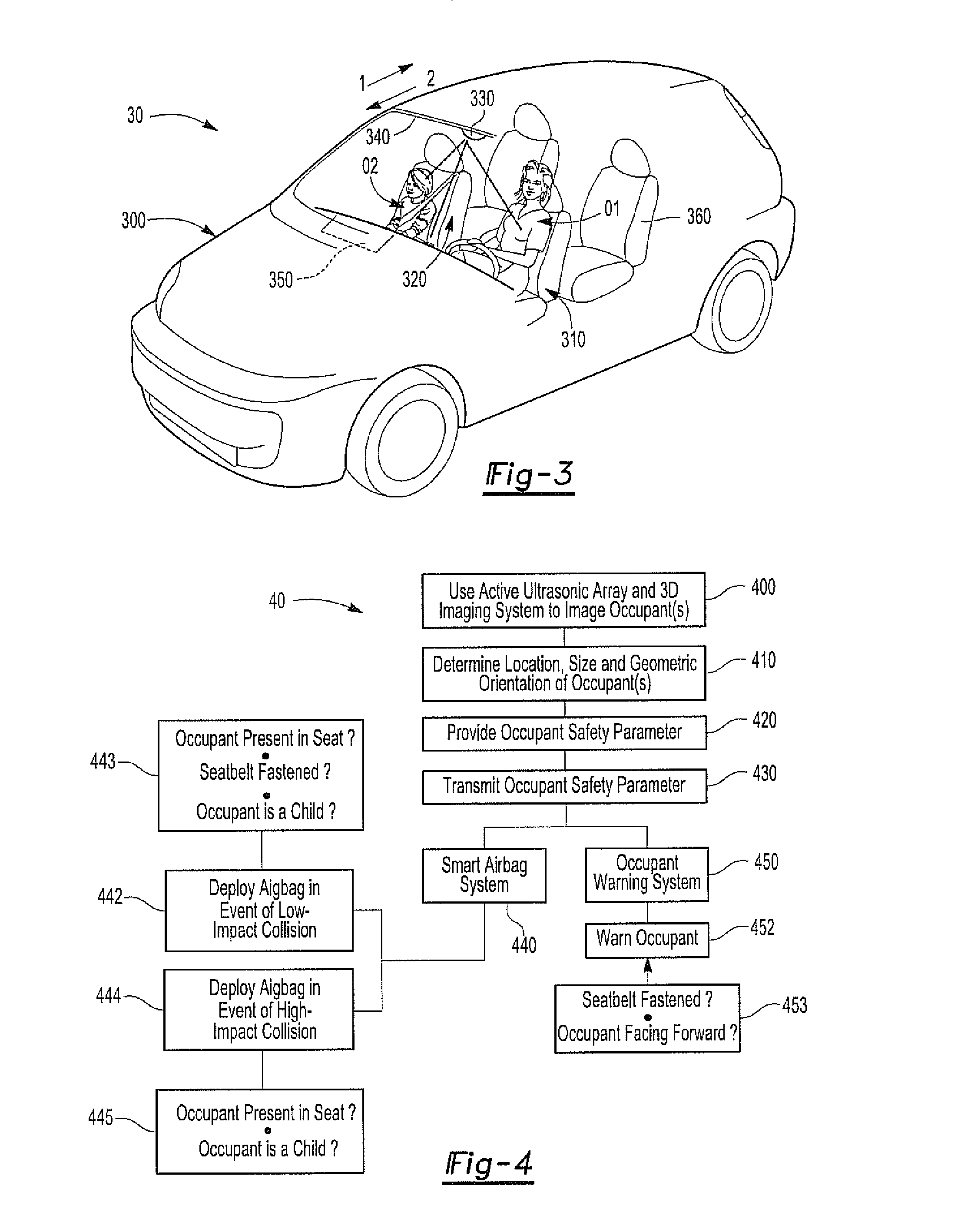
[0009]The occupant safety system can be a smart airbag system with the active safety system affording whether or not an airbag is deployed when a predefined level impact to the motor vehicle occurs. Similarly, the occupant warning system can transmit a warning for an occupant to sit facing forward, to buckle a seatbelt, and the like, based on the occupant safety parameter. In some instances, the 3D imaging circuit can recognize a non-occupant object located on a seat and the active safety system can afford for the non-deployment of an airbag during a predefined level of impact to the motor vehicle when the seat is not occupied or a non-occupant object is recognized on the seat. Likewise, the active safety system can afford for the occupant warning system to not provide a warning to sit facing forward and / or to buckle a seatbelt when the seat is not occupied or a non-occupant object is recognized on the seat.

Problems solved by technology

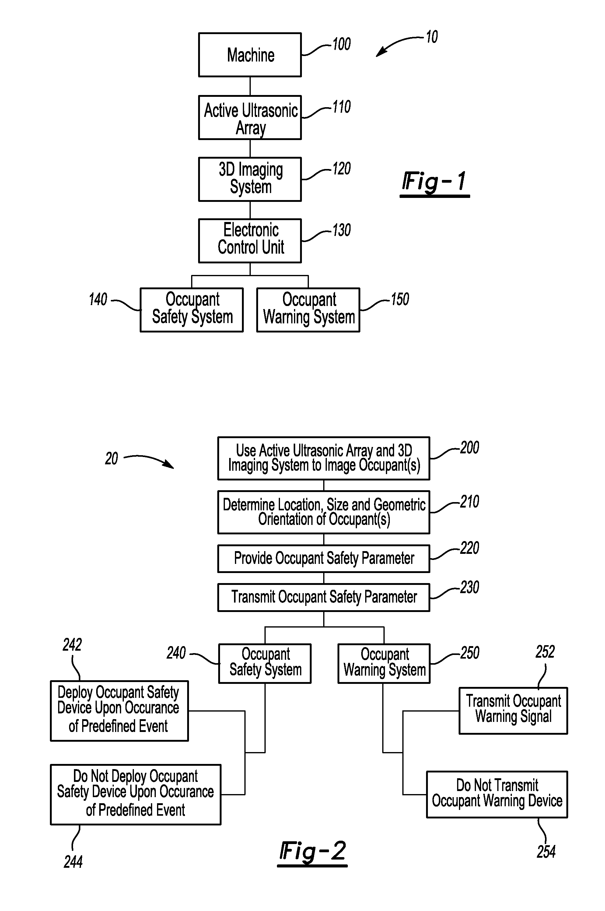
In addition, heavy equipment machinery can have an occupant warning system that alerts a driver of such a machine when an operator of the machinery has been placed in a potentially dangerous and / or unstable position.
However, heretofore systems have been limited with respect to their ability to determine various safety parameter factors about the occupant.
For example, heretofore systems have not determined whether or not an actual person is sitting in a seat of a motor vehicle and thus whether or not an airbag should be deployed in the event of a predefined impact to the vehicle.

Method used


Image

  • Occupant detection and imaging system
  • Occupant detection and imaging system
  • Occupant detection and imaging system

Examples


Embodiment Construction

[0014]The present invention discloses an active safety system for a machine and a process for operating the active safety system. As such, the active safety system and / or the process has utility for improving the safety of an occupant of a motor vehicle, an operator of a machine and the like.

[0015]The active safety system can include an active ultrasonic array that has a plurality of ultrasonic transducers. The plurality of ultrasonic transducers can propagate a plurality of sound waves, receive a plurality of echo waves resulting from the plurality of sound waves bouncing off a surface and transform the plurality of echo waves into a plurality of electrical pulses. In addition, the active ultrasonic array can transmit the plurality of electrical pulses to a three-dimensional (3D) imaging circuit. The 3D imaging circuit can receive the plurality of electrical pulses and generate a 3D image. An electronic control unit, that may or may not be part of the 3D imaging circuit, can determ...


PUM


Abstract

An active safety system for a machine and a process for operating the active safety system are disclosed. The active safety system an active ultrasonic array having a plurality of ultrasonic transducers. The plurality of ultrasonic transducers can propagate a plurality of sound waves, receive a plurality of echo waves and transform the plurality of echo waves into a plurality of electrical pulses. The plurality of electrical pulses can be transmitted to and received by a three-dimensional imaging circuit. The three-dimensional imaging circuit can generate a 3D image from the plurality of electrical pulses and an electrical control unit can determine a location, size and geometric orientation of the 3D image. The electronic control unit can also provide an occupant safety parameter as a function of the location, size and geometric orientation of the 3D image and transmit the occupant safety parameter or an instruction related to the occupant safety parameter to an occupant safety system and / or an occupant warning system.

Description

FIELD OF THE INVENTION[0001]The present invention relates generally to an occupant detection and imaging system. More specifically, the present invention relates to an active safety system for a machine that uses an occupant detection and imaging system in combination with an occupant safety system and / or an occupant warning system.BACKGROUND OF THE INVENTION[0002]Various safety systems are known to help protect and reduce injury of an occupant of a vehicle, an operator of a machine and the like. For example, seatbelts in combination with airbags are used within motor vehicles to prevent or help reduce serious injury of occupants riding therein. In addition, heavy equipment machinery can have an occupant warning system that alerts a driver of such a machine when an operator of the machinery has been placed in a potentially dangerous and / or unstable position.[0003]The use of non-contact sensors to determine the location of an occupant with respect to an interior of a motor vehicle is...

Claims


Application Information

Patent Timeline
Patent Type & Authority Patents(United States)
IPC IPC(8): B60R22/00
CPCB60R21/0134B60R2021/01272B60R2022/4866B60R2022/4816
Inventor YONAK, SERDAR H.SCHMALENBERG, PAUL D.
Owner TOYOTA MOTOR CO LTD
Learn More