
Charging holder for a non-lethal projectile

a projectile and charging holder technology, applied in the field of projectiles, can solve the problems of imposing the bullet at substantial velocity towards the target, the death of the person or the living creature, and the gas pressure building inside the casing

Inactive Publication Date: 2012-09-11
GARG RAKESH
View PDF7 Cites 35 Cited by
  • Summary
  • Abstract
  • Description
  • Claims
  • Application Information

AI Technical Summary

Benefits of technology

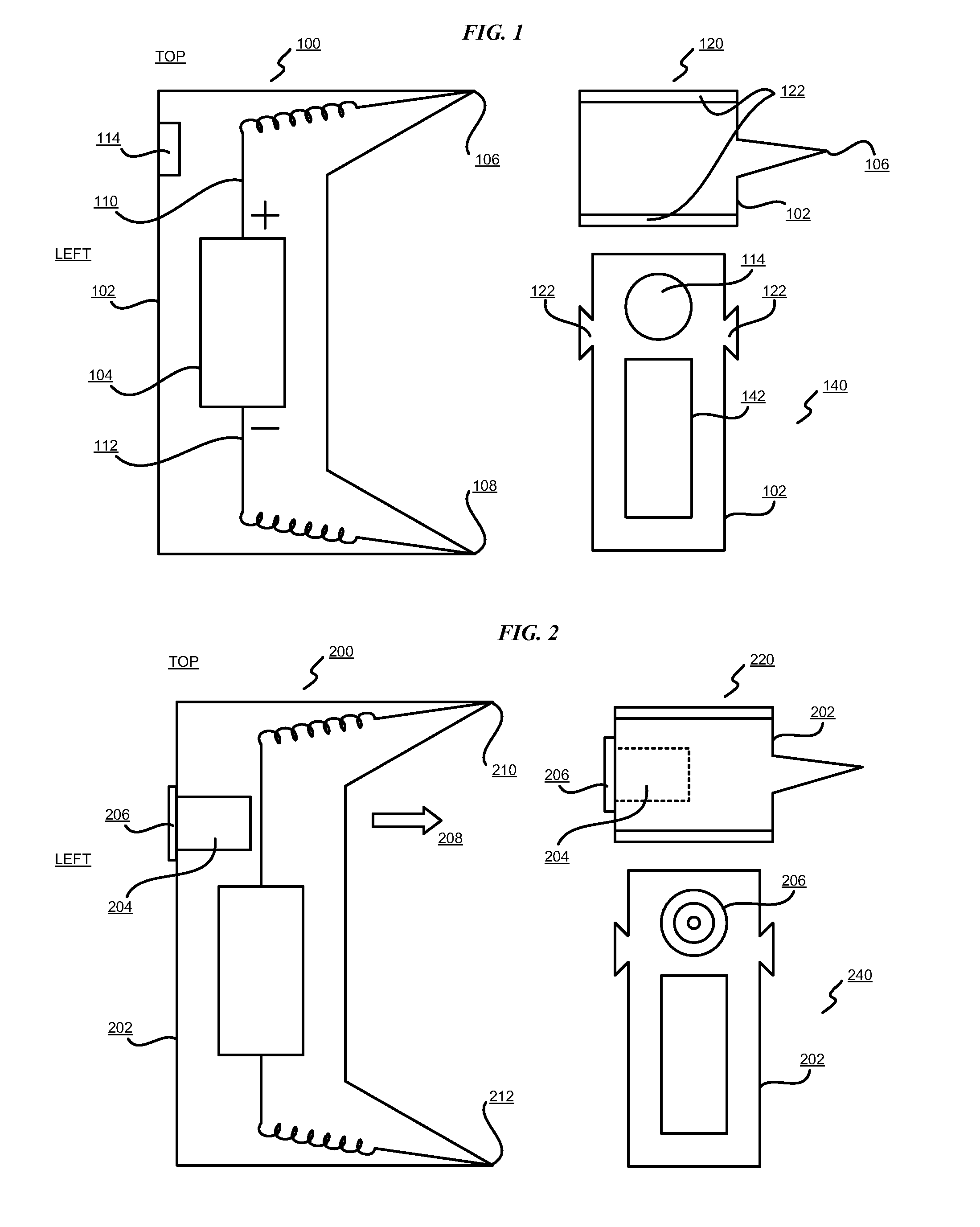
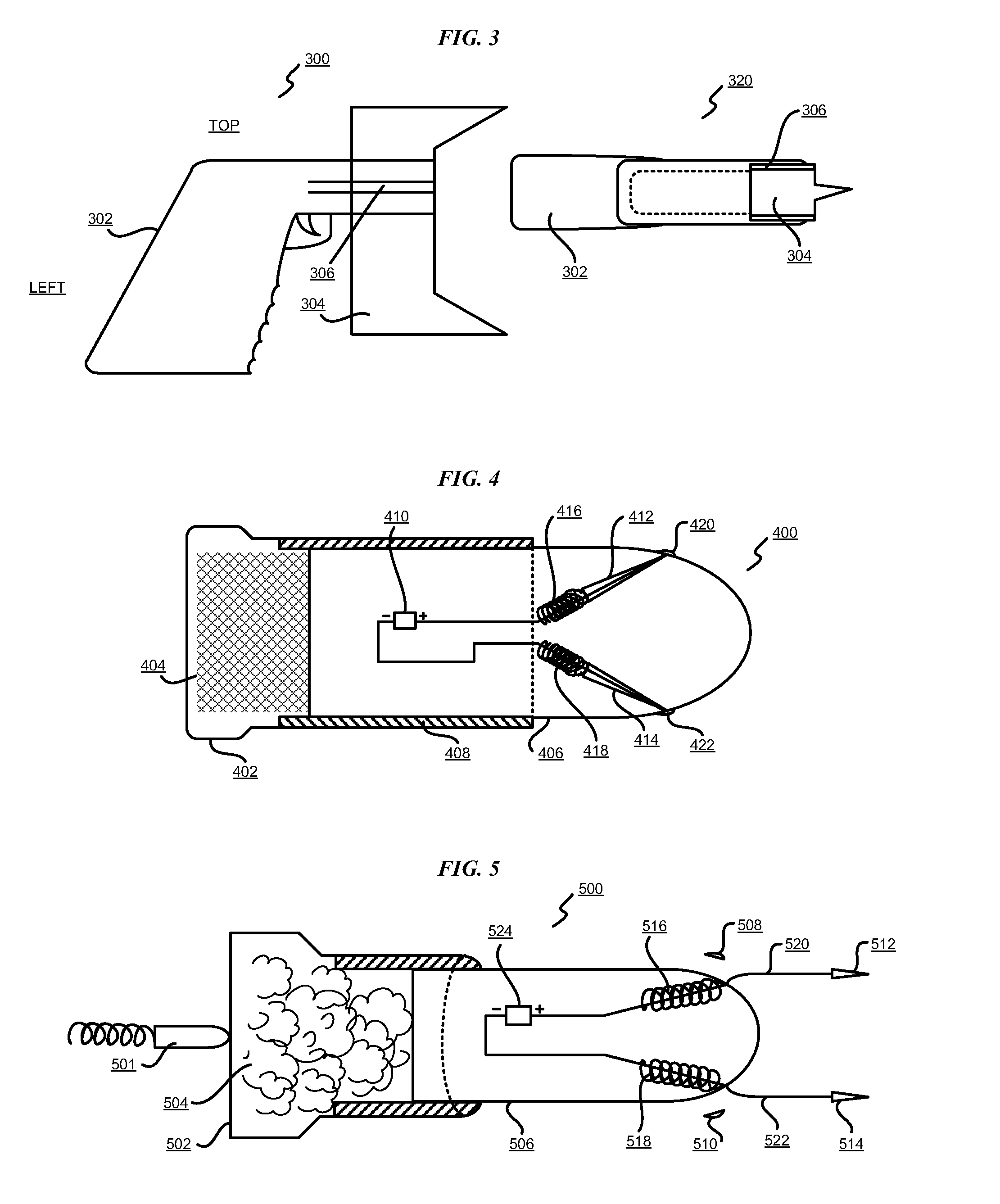
"The patent describes a non-lethal projectile that can be fired from a conventional ammunition cartridge. The non-lethal projectile has electrodes and an electrical power source, which can provide electrical current to the electrodes. The non-lethal projectile can detach from the launching device and can be recharged and reused in another ammunition cartridge. The non-lethal projectile can also be charged using a charging base or a portable electrical power source. The technical effect of this invention is to provide a safer alternative to traditional ammunition that can cause permanent harm to the target."

Problems solved by technology

Lethal ammunition is a type of ammunition that when used against a target, such as a person or another living creature, can cause death of the person or the living creature.
When the closed end of the casing is struck, such as with a firing pin or a hammer of a firearm, the explosive power ignites, causing gas pressure to build inside the casing and forcing the bullet at substantial velocity towards a target.
The bullet is generally designed to cause physical impact or penetration into the target, thereby delivering deadly force to the target.

Method used


Image

  • Charging holder for a non-lethal projectile
  • Charging holder for a non-lethal projectile
  • Charging holder for a non-lethal projectile

Examples


Embodiment Construction

[0038]The illustrative embodiments recognize that presently available non-lethal weapons are limited in range over which they can deliver the non-deadly force. For example, a Tazer gun has to be fired from a distance no greater than the length of the wire, generally only a few feet, that is propelled from the Tazer gun. A stun gun has to be placed directly in contact with the target. The illustrative embodiments recognize that the distance between the user of the non-deadly weapon and the target is a factor that affects the safety of the user. The closer the user is to the target, the greater is the chance that the user may lose control of the weapon to the target, or suffer harm from the target.

[0039]The illustrative embodiments further recognize that the distance is also a factor in the effectiveness of the weapon. For example, if the presently available non-lethal weapon is farther away from the target than the length of the electrode or the wires connected thereto, the electrode...


PUM


Abstract

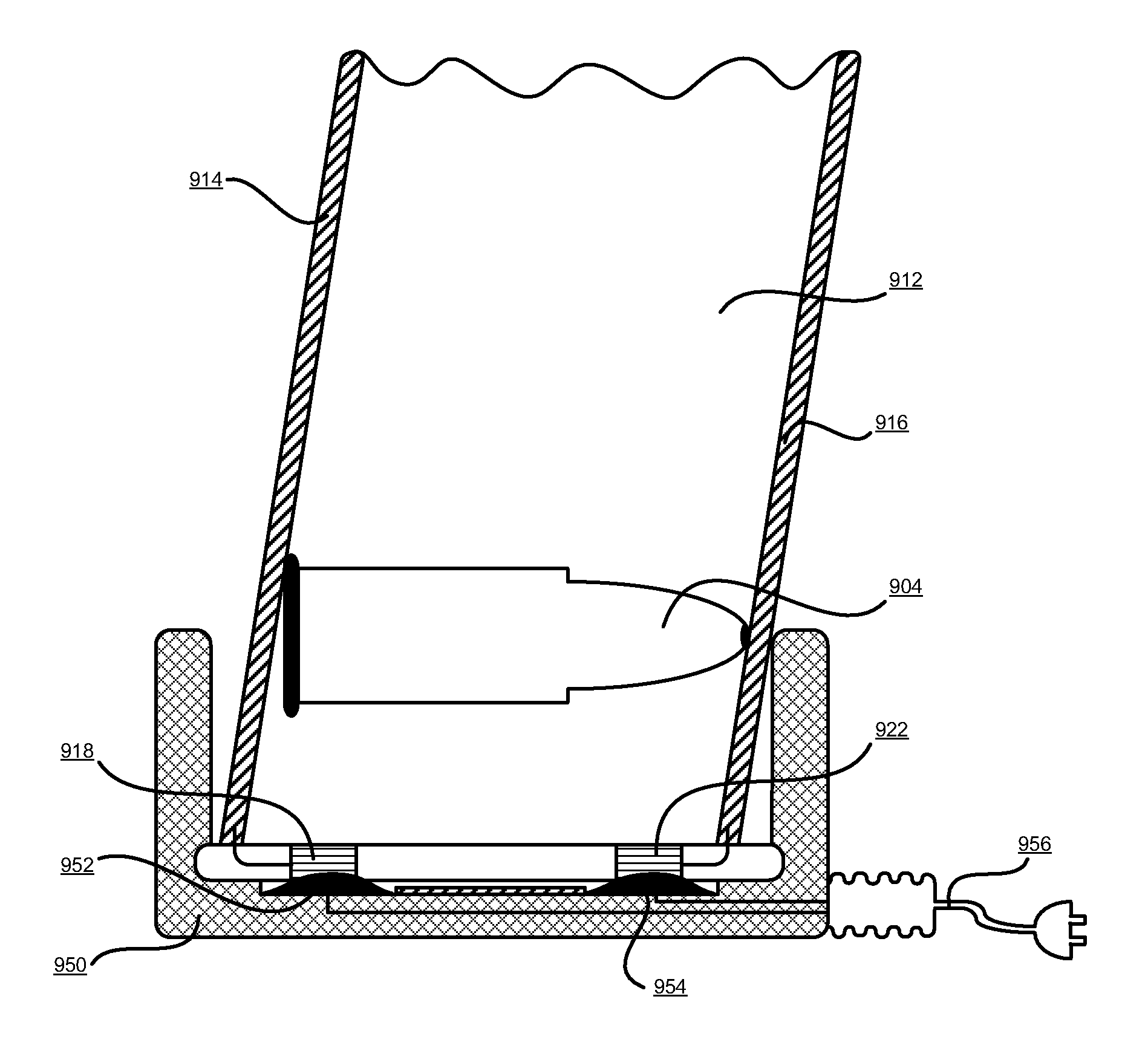
A non-lethal projectile, and a storage and charging mechanism therefor are provided in the illustrative embodiments. An ammunition cartridge includes a propulsion mechanism and a non-lethal projectile. The non-lethal projectile is configured to detach from a launching device when propelled from the launching device, and includes a set of electrodes electrically coupled to an electrical power source. The electrical power source may be a capacitor, a battery, or a combination thereof, and may be rechargeable. The ammunition cartridge may be shaped and sized for firing from a weapon designed to fire a comparably shaped and sized conventional ammunition. A holder for holding and charging a non-lethal projectile in an ammunition cartridge includes a set of conductors to provide a charging current to the electrical power source in the non-lethal projectile. A charging base may receive the holder and provide electrical power to the set of conductors.

Description

BACKGROUND OF THE INVENTION[0001]1. Field of the Invention[0002]The present invention relates generally to a projectile, and in particular, to a projectile for use in a weapon or a launching device. Still more particularly, the present invention relates to a non-lethal projectile for use in conjunction with a lunching device.[0003]2. Description of the Related Art[0004]Traditional weapons, such as handguns, rifles, automatic or semi-automatic fire weapon systems, and other firearms use lethal ammunition. A weapon is a device that can be used for defensive or aggressive application of force, generally deadly force, by launching a projectile from the device towards a target. A target is a person or an object towards which the force is directed.[0005]Ammunition is a combination of a projectile and a mechanism to generate propulsion in a container suitable for use with a weapon. Lethal ammunition is a type of ammunition that when used against a target, such as a person or another living...

Claims


Application Information

Patent Timeline
Patent Type & Authority Patents(United States)
IPC IPC(8): F42B12/02F41B15/00
CPCF41A9/65F41H13/0031F42B12/36
Inventor GARG, RAKESH
Owner GARG RAKESH
Learn More