
Fuel cell system and control method thereof

a fuel cell and control method technology, applied in the field of fuel cell systems, can solve the problem of not decreasing fuel utilization efficiency, and achieve the effect of shortening the temperature rise time and reducing fuel utilization efficiency

Inactive Publication Date: 2012-09-11
YAMAHA MOTOR CO LTD
View PDF28 Cites 2 Cited by
  • Summary
  • Abstract
  • Description
  • Claims
  • Application Information

AI Technical Summary

Benefits of technology

This approach allows for a faster temperature rise and increased power generation without decreasing fuel utilization efficiency, optimizing the start-up process and maintaining system stability.

Problems solved by technology

Further, since heating is not provided by oxidization of the aqueous fuel solution, fuel utilization efficiency does not decrease.

Method used


Image

  • Fuel cell system and control method thereof
  • Fuel cell system and control method thereof
  • Fuel cell system and control method thereof

Examples


Embodiment Construction

[0034]Hereinafter, preferred embodiments of the present invention will be described with reference to the drawings.

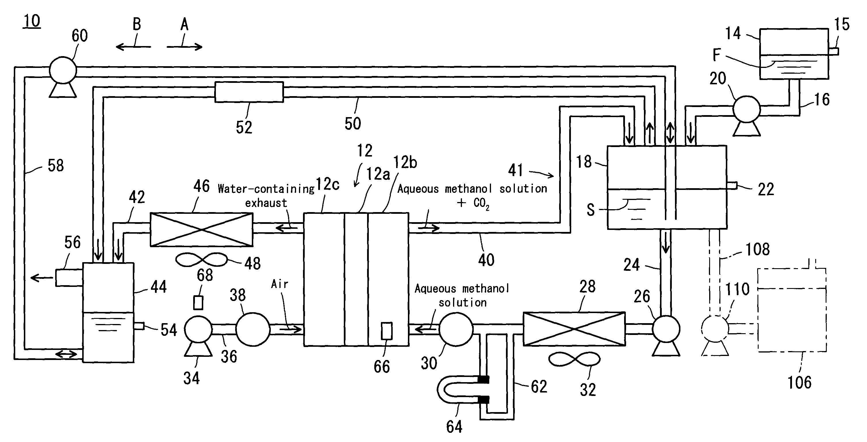
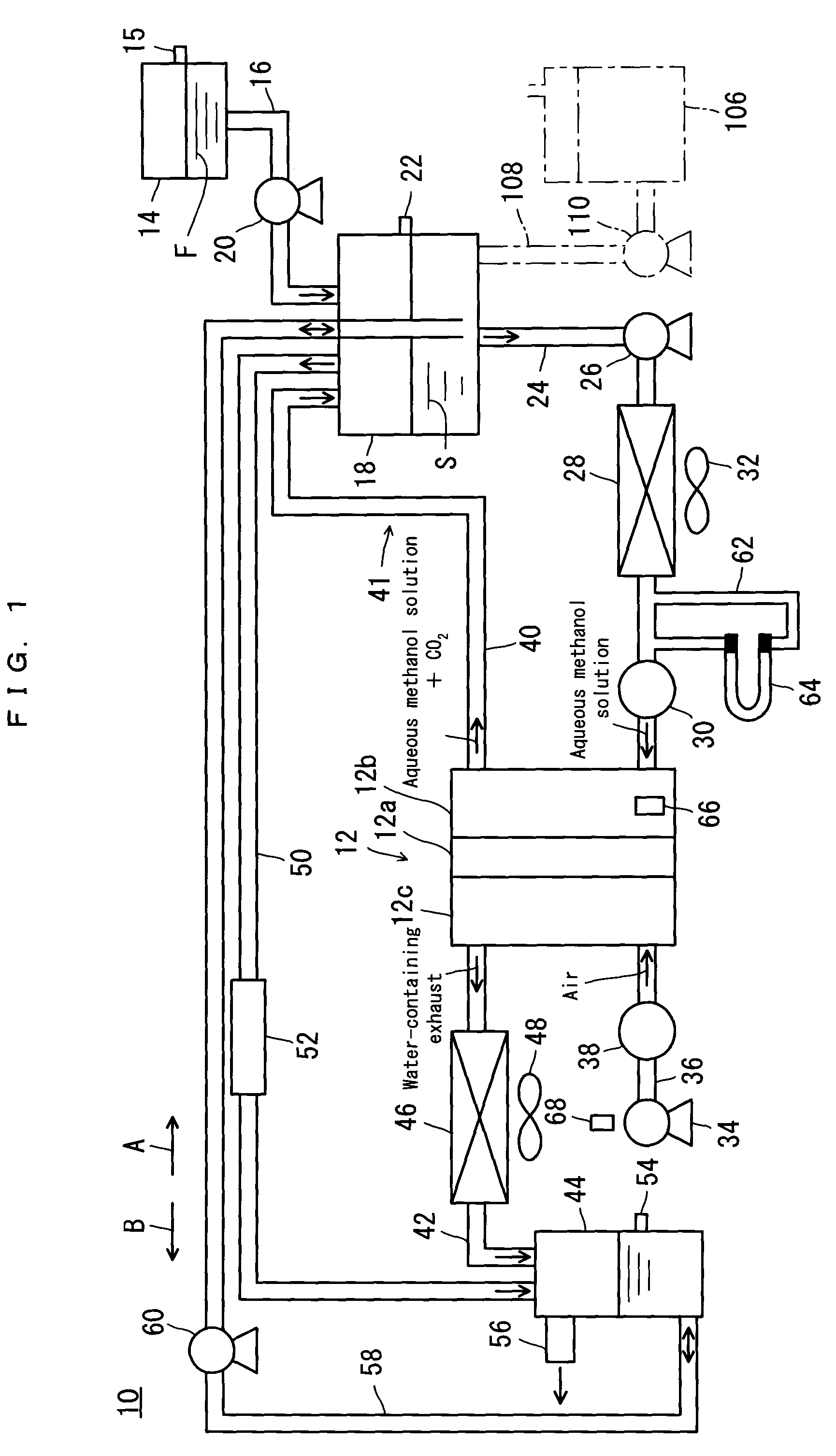
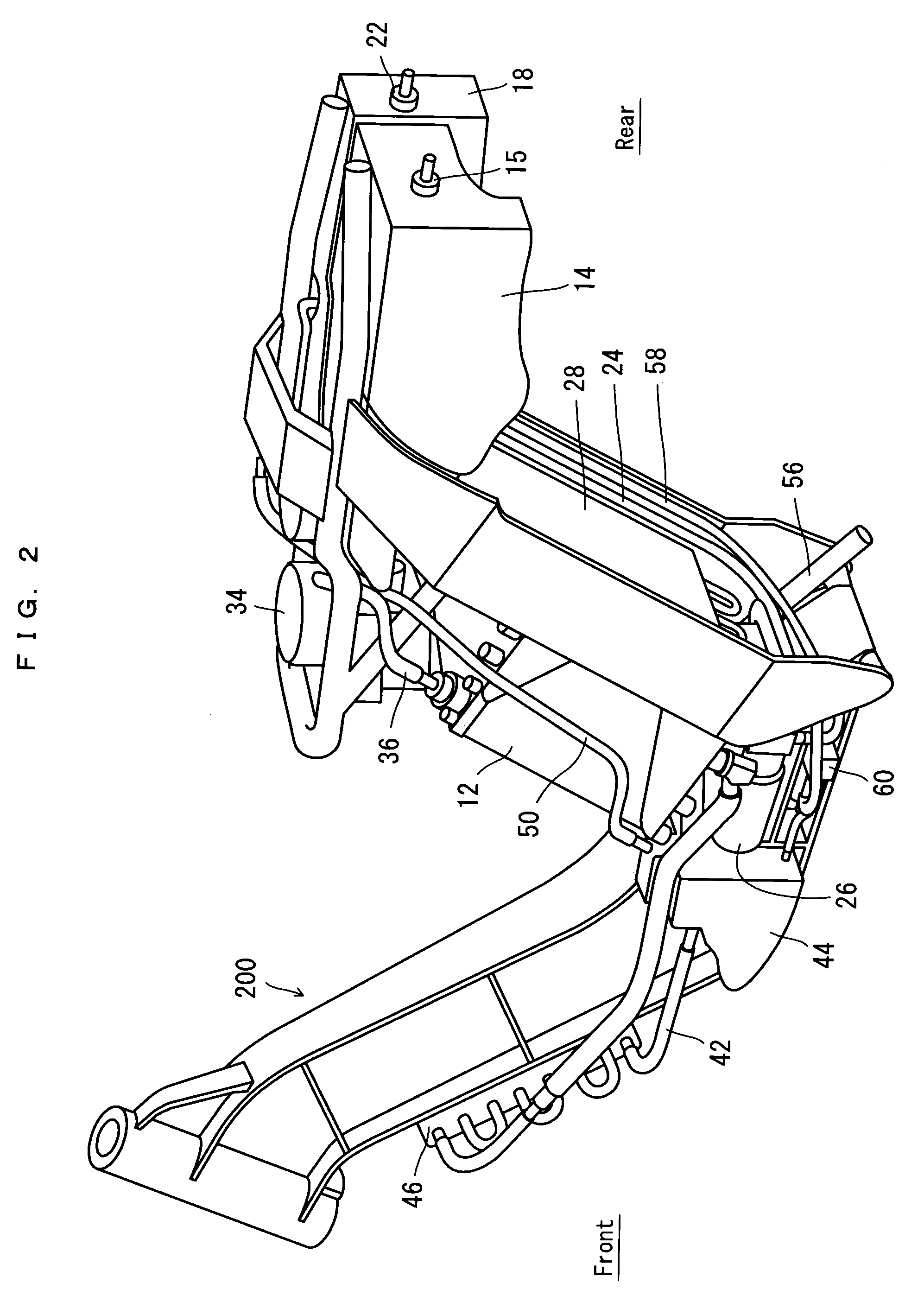
[0035]As shown in FIG. 1 through FIG. 4, a fuel cell system 10 according to a preferred embodiment of the present invention is a direct methanol fuel cell system. Direct methanol fuel cell systems do not require a reformer and so can be utilized suitably in equipment which requires portability, as well as in equipment in which size reduction is desirable. In the present description, the fuel cell system 10 is preferably used on a motorbike as an example of transportation equipment. Note, however, that the motorbike is represented only by a vehicle frame 200 as shown in FIG. 2. Note also that as in FIG. 2, the left side of the diagram represents the front of the vehicle while the right side represents the rear of the vehicle. Further, the fuel cell system 10 is disposed along the vehicle frame 200.

[0036]Referring mainly to FIG. 1, the fuel cell system 10 includes a fuel ...


PUM

PropertyMeasurementUnit
temperatureaaaaaaaaaa
aqueousaaaaaaaaaa

Abstract

A fuel cell system includes a fuel cell which has an anode. A fuel supplying device circulates a supply of aqueous methanol solution to the anode in the fuel cell. The fuel supplying device includes an aqueous solution tank for storing the aqueous methanol solution. By moving aqueous methanol solution from the aqueous solution tank to a water tank, the amount of aqueous methanol solution which is in circulation at the time of start-up is made smaller than the amount for normal operation. The fuel cell system and a control method therefore are capable of shortening a time that is necessary for heating aqueous fuel solution to be supplied to the fuel cell to a predetermined temperature without reducing fuel utilization efficiency.

Description

BACKGROUND OF THE INVENTION[0001]1. Field of the Invention[0002]The present invention relates to fuel cell systems and methods for controlling the same. More specifically, the present invention relates to a fuel cell system which circulates a supply of aqueous fuel solution to an anode of a fuel cell, and a method of controlling the fuel cell system.[0003]2. Description of the Related Art[0004]Recently, there has been a desire in the field of direct methanol fuel cell systems that the time from start-up to full power generation should be shortened. As one solution, it has been disclosed to shorten a temperature rise time in which the aqueous methanol solution supplied to the fuel cell reaches a predetermined temperature.[0005]For example, JP A 2004-55474 (Patent Document 1) discloses a technique in which a temperature raising device is provided between a fuel storing portion and a cell stack, and a portion of the aqueous methanol solution in the fuel storing portion is supplied to t...

Claims


Application Information

Patent Timeline
Patent Type & Authority Patents(United States)
IPC IPC(8): H01M8/04
CPCH01M8/04186H01M8/04223H01M8/1011Y02E60/50H01M8/04225H01M8/04302
Inventor MURAMATSU, YASUYUKIOISHI, MASATSUGU
Owner YAMAHA MOTOR CO LTD
Learn More