
Method and apparatus for efficient automated re-contouring of four-dimensional medical imagery using surface displacement fields

a surface displacement field and automatic re-contouring technology, applied in the field of medical images, can solve the problems of inaccurate contouring, long processing time, and tedious manual contouring of these images, and achieve the effects of improving computational efficiency, shortening processing time, and enhancing computational efficiency

Active Publication Date: 2012-09-11
IMPAC MEDICAL SYST
View PDF21 Cites 8 Cited by
  • Summary
  • Abstract
  • Description
  • Claims
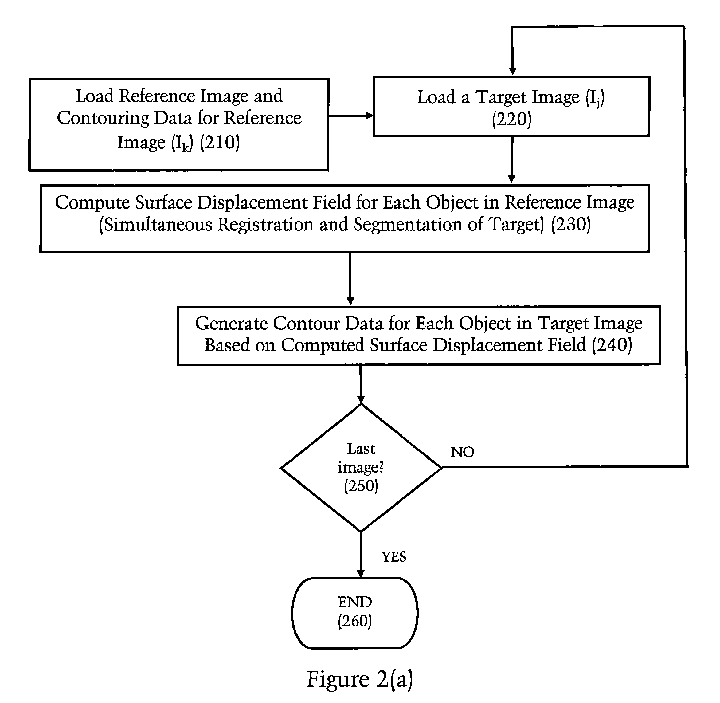
  • Application Information

AI Technical Summary

Benefits of technology

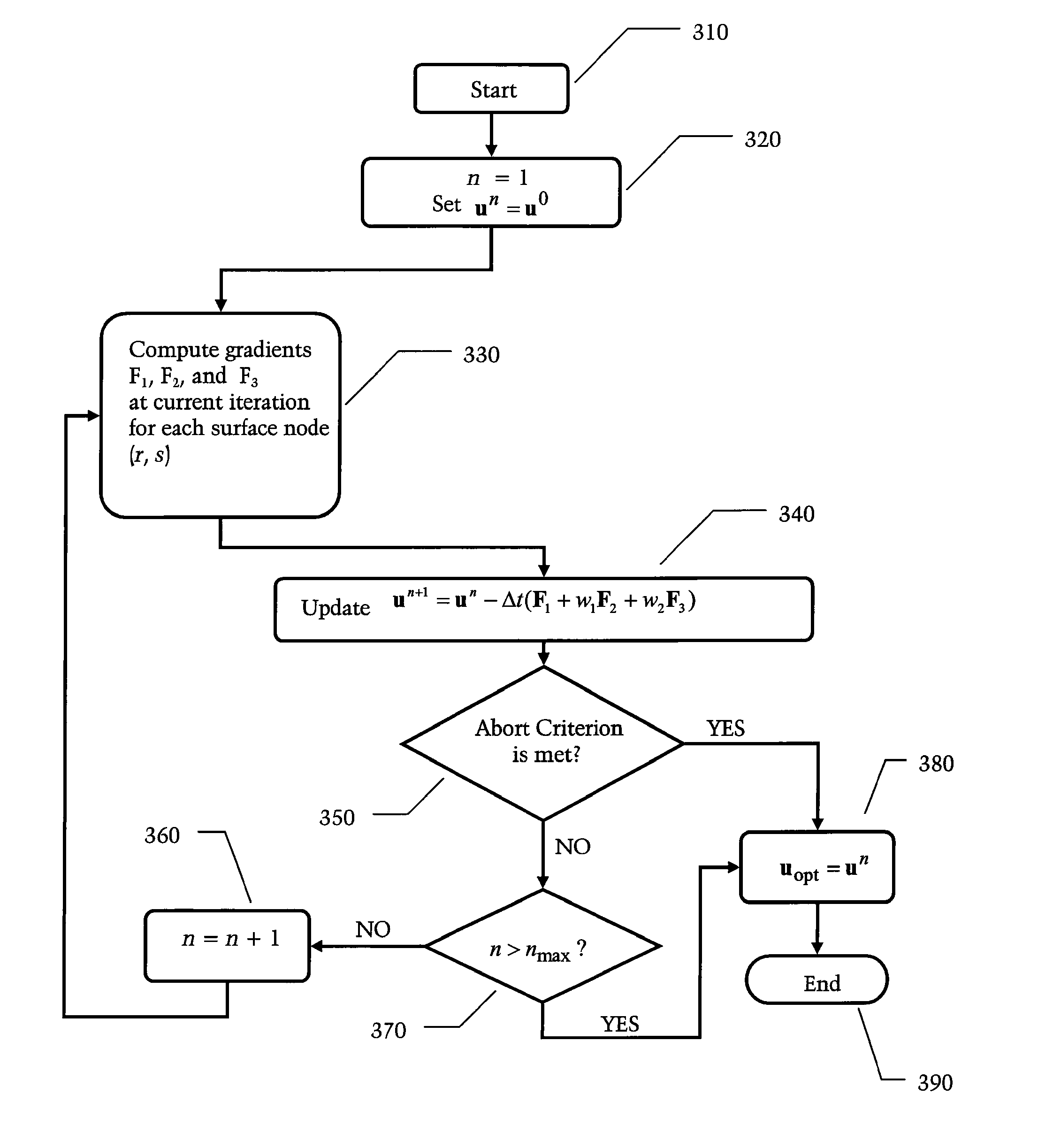
[0008]Current image processing software programs known to the inventors herein are believed to perform image registration and segmentation separately. In an exemplary embodiment, the inventors disclose an innovative technique for the automatic re-contouring of images based on simultaneous image registration and segmentation. By making use of pre-existing contouring data for the reference image, it is possible to provide improved accuracy in contouring the target image(s). Moreover, due to improved computational efficiency, an embodiment of the present invention is able to provide this improved accuracy while also providing shorter processing times.
[0009]When contouring a plurality of time-series images, it is believed that conventional contour-generating software ignores the contouring information available from computing the contouring information for one of these images when computing the image registration and segmentation of another image in the series. By taking into account the contouring information available with respect to the reference image, the inventors believe that the accuracy of re-contouring results can be improved.
[0010]In an embodiment of the present invention, the contouring information for the reference image is used as a starting point for an automated re-contouring process. Computer software can be used to calculate a surface displacement field. The surface displacement field defines the correspondence between points on the contour surface in the reference image and points on the new contour surface in the target image. The surface displacement field provides both the correspondence between the reference image and the target image (registration) and the location of objects of interest within the target image (segmentation). Therefore, it can be said that the calculation of the surface displacement field achieves a simultaneous image registration and segmentation. This surface displacement field preferably defines a vector field which can be used to map the contoured structures in the reference image onto the target image. Preferably, one surface displacement field is calculated for each object of interest in the reference image. The surface displacement field approach yields many advantages, as will be apparent from the detailed description below.
[0011]In an exemplary embodiment of the present invention, the surface displacement field is only computed at points of the already-delineated object boundaries in the reference image. Current contour-generating software is believed to redundantly compute the correspondence map for every point in the reference image during registrations. By computing the surface displacement field only at points on the already-delineated object boundaries, this embodiment achieves improved computational efficiency and shorter processing time. Thus, the inventors believe that traditional 4D re-contouring approaches use deformable image registration techniques which are formulated to answer the question: “What is the best match (in the target image) for every point in the reference image?” Instead, a preferred embodiment disclosed herein seeks to answer the question: “What is the best match (in the target image) for every point on the surface of the object desired to be found in the target image?” In providing an answer to this question, the preferred embodiment is believed to greatly enhance computational efficiency. While a preferred solution to the inventors' question as disclosed herein involves consideration of more points than just the object surface points from the reference contour (for example, an exemplary embodiment considers all points inside the object surface for histogram matching and also considers points in a neighborhood of the object surface for an image gradient computation), the inventors note that the total number of points considered with such processing will still only be a small part of the whole image; this is particularly true when contouring small objects such as a tumor.
[0012]In yet another exemplary embodiment of the present invention, a multi-resolution implementation is disclosed. In this embodiment, the surface displacement field is computed at multiple resolutions of each target image. First, the reference and target images are down-sampled to a coarse resolution. The surface displacement field is then calculated for this coarse resolution. Preferably, this “coarse-level” surface displacement field is used as the starting point for the surface displacement field calculation at the next finer resolution. Preferably, this process is repeated for a plurality of resolutions (e.g., three resolutions corresponding to coarse, medium, and fine (original) resolutions). By computing the surface displacement field at lower resolutions in this manner, the present invention is able to better capture large deformations in objects of interest.

Problems solved by technology

Due to the large number of images involved in 4D radiotherapy, manual contouring of these images is extremely tedious and time-consuming.
Several methods have been proposed, but these methods suffer from the drawbacks of long processing times and / or inaccurate contouring results.
Current contour-generating software is believed to redundantly compute the correspondence map for every point in the reference image during registrations.

Method used


Image

  • Method and apparatus for efficient automated re-contouring of four-dimensional medical imagery using surface displacement fields
  • Method and apparatus for efficient automated re-contouring of four-dimensional medical imagery using surface displacement fields
  • Method and apparatus for efficient automated re-contouring of four-dimensional medical imagery using surface displacement fields

Examples


Embodiment Construction

I. Contours:

[0023]Contours are planar, closed curves C(x,y,z) which can be realized as sets of non-uniformly sampled points along the user-input stroke, {c1, . . . ,cM} (or sets of points generated by an auto-thresholding and / or auto-segmentation program), wherein the individual points are represented by ci=C(xi,yi,zi), and wherein M is the number of points in the contour. Points ci in the T planes (xz-planes) have y constant, S contours (yz-planes) have x constant, and C contours (xy-planes) have z constant.

[0024]Contours can also be parameterized by a curve length u where the curve C of length L is represented as C(x,y,z)=C(x(u),y(u),z(u))=C(u) where 0≦u≦L and C(0)=C(L).

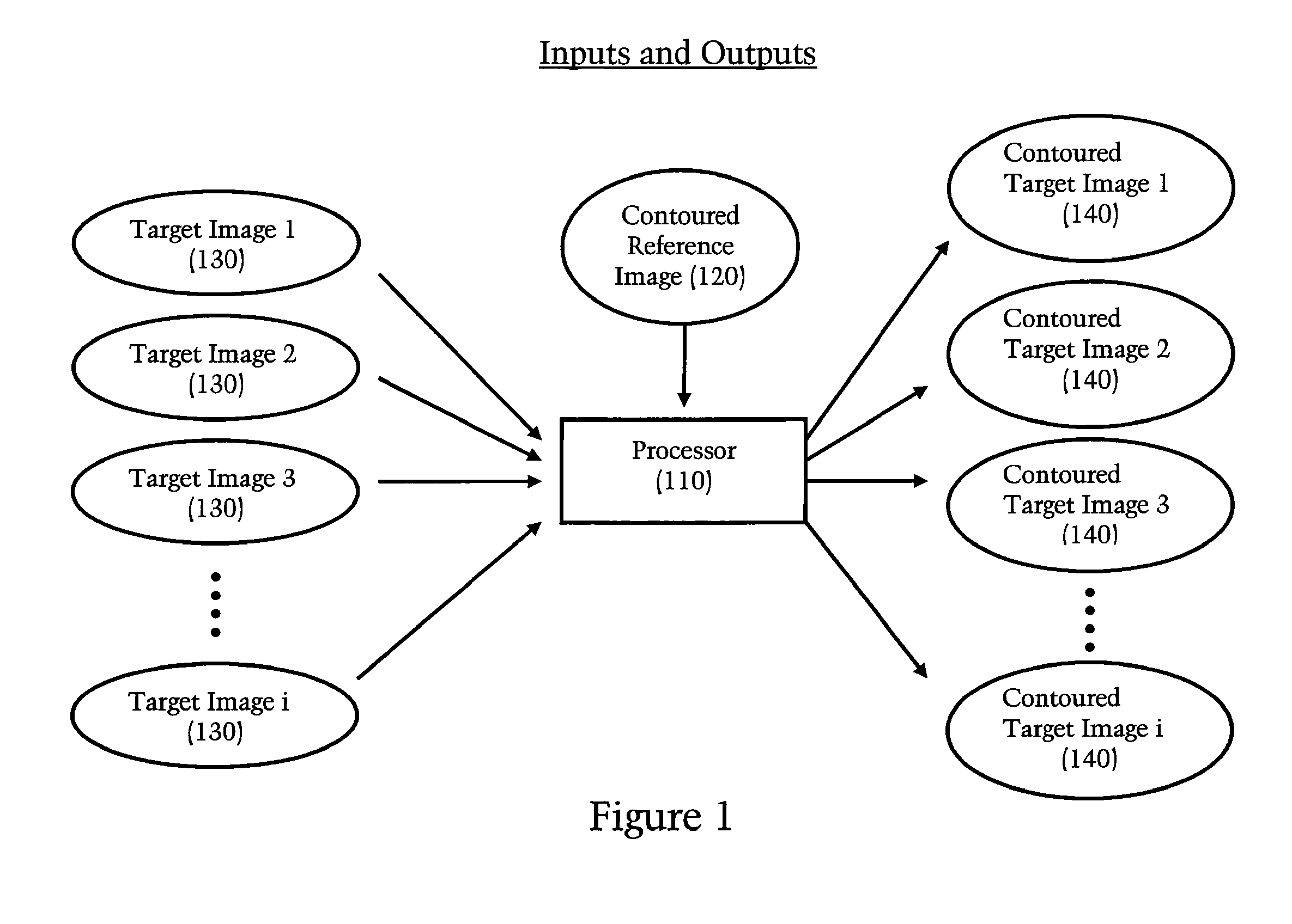
[0025]FIG. 1 depicts a basic overview of the inputs and outputs for an exemplary embodiment of the present invention. The inputs preferably comprise (a) a reference image 120 for which contour data is available (for example, reference image 120 has been manually contoured by a doctor using known manual contouring s...


PUM


Abstract

A technique is disclosed for generating a new contour and / or a 3D surface from contour data using a surface displacement field. The technique is preferably applied to un-contoured target images within a 4D image sequence for which contour data is desired. The technique can be initialized with contour data related to a reference image that has already been contoured, e.g. by a doctor who manually enters contour information into a computer. Image registration (calculation of correspondence between the reference image and target image) can be performed simultaneously with segmentation (identifying regions of interest in the target image). This allows one to make use of segmentation information in a reference image to improve the accuracy of contouring within the target image.

Description

FIELD OF THE INVENTION[0001]The present invention pertains generally to the field of processing medical images, particularly generating contours for four-dimensional (4D) medical imagery.BACKGROUND AND SUMMARY OF THE INVENTION[0002]“Contouring” refers to identifying and delineating objects or structures in images by way of contours corresponding to such objects / structures. Contouring is an important part of radiation therapy planning (RTP), wherein treatment plans are custom-designed for each patient's anatomy. Contours are often obtained “manually” in response to user input, wherein a user traces the object boundary on the image using a computer workstation's mouse and screen cursor. Contours can also be obtained via automated processes such as auto-thresholding programs and / or auto-segmentation programs. The process of delineating or “contouring” structures within an image is known in the field as “image segmentation.”[0003]With the recent advent of “4D radiotherapy” or “adaptive ...

Claims


Application Information

Patent Timeline
Patent Type & Authority Patents(United States)
IPC IPC(8): G06K9/34G06V10/46
CPCG06K9/48G06K9/6207G06V10/46G06V10/755
Inventor HAN, XIAOHIBBARD, LYNDON S.BRAME, RYAN SCOTT
Owner IMPAC MEDICAL SYST
Learn More