Condensation dryer having a heat pump and method for the operation thereof

Inactive Publication Date: 2012-09-18
BSH BOSCH & SIEMENS HAUSGERAETE GMBH
View PDF16 Cites 30 Cited by
  • Summary
  • Abstract
  • Description
  • Claims
  • Application Information

AI Technical Summary

Benefits of technology

[0014]An object of the invention is thus to provide a condensation dryer with a heat pump, which dryer has an increased useful life and offers the possibility of easier cleaning.

Problems solved by technology

Said drying process is very energy-intensive, since the heat removed to cool the process air in the heat exchanger is lost to the process from the energy perspective.
The use of a heat pump gives rise to the problem of soiling of both heat exchangers in the heat pump (evaporator, condenser), especially the evaporator, by entrained fluff.
Unfortunately the fluff contained in the process air cannot be completely separated out in the fluff filter, since an improvement in the filtration effectiveness of the fluff filter is accompanied by an increase in its flow resistance.
As the evaporator and condenser of a heat pump are generally permanently installed, and connected to the compressor by means of pressure-tight piping, they cannot be removed for cleaning.
A further problem lies in the pipework between heat exchangers and compressor.
In addition, the heat exchangers cannot be optimally positioned in the process airstream, since otherwise the coolant lines become too long.
Furthermore, the industrial manufacture of the system comprising compressor, evaporator and condenser together with the high pressure lines that connect them is very difficult to realize cost-effectively.
Similar problems arise in the case of other coolants employed in heat pumps.
These disadvantages of known condensation dryers with heat pumps result in reduced useful life, and in a less favorable energy balance due to poor cleaning options for the heat exchangers.

Method used


Image

  • Condensation dryer having a heat pump and method for the operation thereof
  • Condensation dryer having a heat pump and method for the operation thereof

Examples


Embodiment Construction

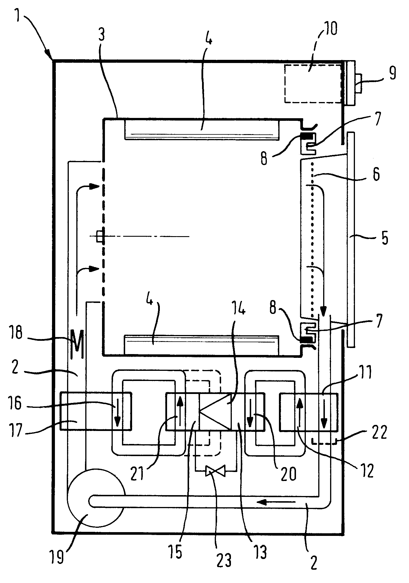
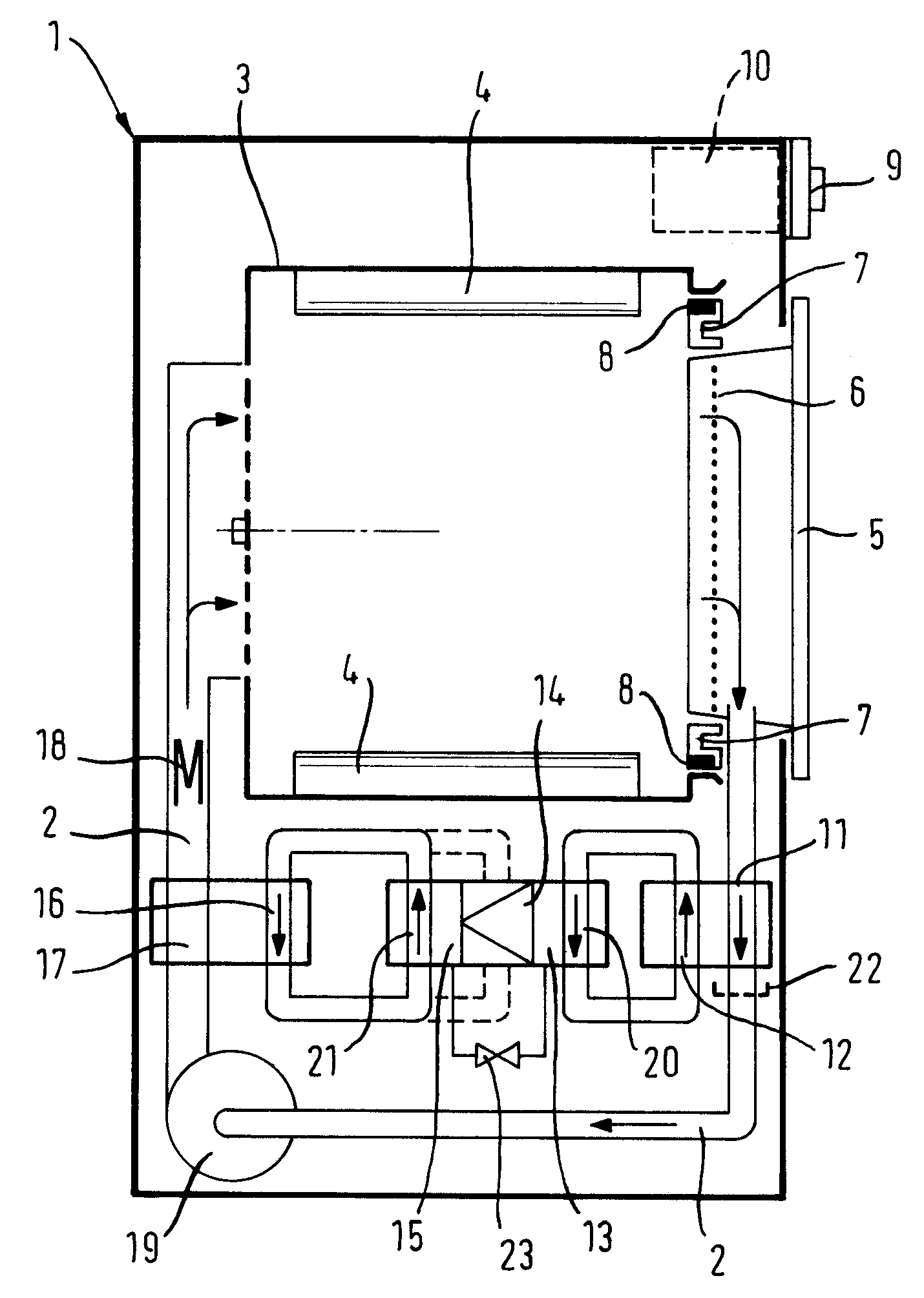
[0041]In the condensation dryer in FIG. 1, the heat pump is connected to the process air circuit via two secondary fluid circuits.

[0042]FIG. 1 shows a vertical section through a condensation dryer 1 (hereinafter referred to as “dryer”1). The dryer 1 represented in FIG. 1 has a drum 3 which is rotatable around a horizontal axis, as a drying chamber 3, within which are fixed agitators 4 for moving laundry during a drum rotation. A heater 18, a first heat exchanger 11, 12, 13, a heat pump 13, 14, 15, 23, a second heat exchanger 16, 17 and a fan 19 are provided in order to generate a process air circuit 2, which is closed by an air duct 2, through the drum 3, to cool this after its passage through the drum 3, and after condensation of the moisture contained in the process air to heat it again. Here, air heated by the heater 18 is directed from the rear, that is from the side of the drum 3 opposite the door 5 of the dryer, through its perforated base into the drum 3, there comes into con...


PUM


Abstract

A condensation dryer is provided that includes a drying chamber for items to be dried, a process air circuit via which fan driven process air can be conducted across the items to be dried, and a heat pump circuit for alternately heating and cooling the process air. A secondary fluid circuit is provided between the process air circuit and the heat pump circuit.

Description

BACKGROUND OF THE INVENTION[0001]The invention relates to a condensation dryer with a drying chamber for items to be dried, a process air circuit, in which the process air can be conducted across the items to be dried by means of a fan, and a heat pump circuit for alternately heating and cooling the process air.[0002]The invention further relates to a method for operating such a condensation dryer.[0003]Laundry dryers, the operating principle of which is based on the condensation of the evaporated moisture from the laundry by means of warm process air—known as condensation dryers—are very popular because they generate no moisture-laden exhaust air and require no hose to vent this exhaust air from a building in which such a laundry dryer is installed. Condensation dryers can therefore be employed in internally located bathrooms or utility rooms of larger residential complexes.[0004]In a condensation dryer, process air is directed by means of a fan via a heating device into the drum c...

Claims


Application Information

Patent Timeline
IPC IPC(8): F26B5/08
CPCD06F58/206D06F58/24
Inventor STEINER, DIETMAR
Owner BSH BOSCH & SIEMENS HAUSGERAETE GMBH
Why Eureka
Try Eureka