Eureka AIR delivers breakthrough ideas for toughest innovation challenges, trusted by R&D personnel around the world.

Solar panel roof surface

a solar panel and roof cover technology, applied in the field of solar panel roof cover, can solve the problems of partially deferring the substantial cost of solar panels, solar panel systems do not provide a roof cover,

Active Publication Date: 2012-09-18
2192780 ONTARIO OA GALAXY ENERGY AMERICAS
View PDF6 Cites 35 Cited by
  • Summary
  • Abstract
  • Description
  • Claims
  • Application Information

AI Technical Summary

Benefits of technology

"The present invention is a solar panel roof system that includes a roof support substructure with parallel hollow support beams and solar panels that are secured to the support beams to form a closed sloped roof surface. The solar panels are positioned and supported to define elongate segments or strips of abutting panels that allow water to flow over adjacent panels and along the length of the elongate segment. The hollow support beams have a top surface with shallow elongate drainage channels and gasket-receiving slots for draining water. Each panel includes a frame that is supported by adjacent hollow beams with drainage holes in the frame. The solar panels have a relatively low light transmission of about 5%. The technical effects of the invention include improved drainage of water, improved structural stability, and increased light transmission."

Problems solved by technology

The solar panel systems do not provide a roof cover that fulfills the function of protecting against the wind and directing rain and other moisture off the roof.
With this arrangement, the substantial cost of the solar panels is partially deferred due to their dual function of providing a roof cover and power generation.

Method used


Image

  • Solar panel roof surface
  • Solar panel roof surface
  • Solar panel roof surface

Examples


Embodiment Construction

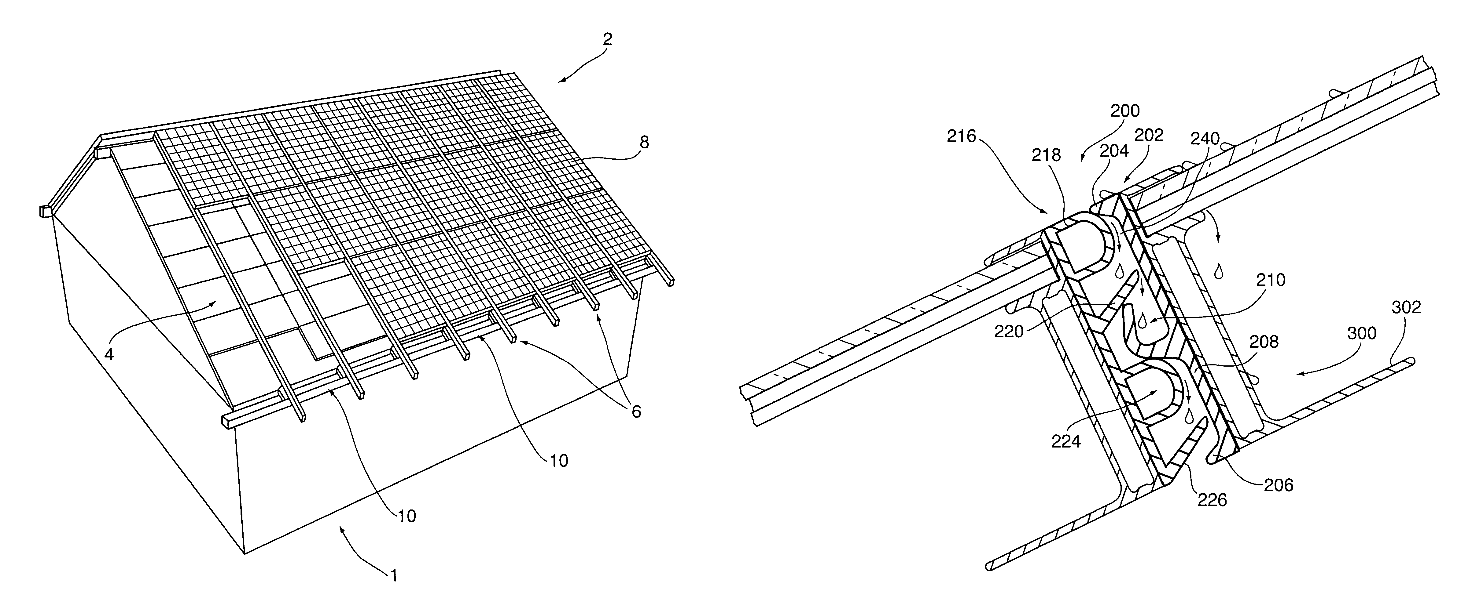
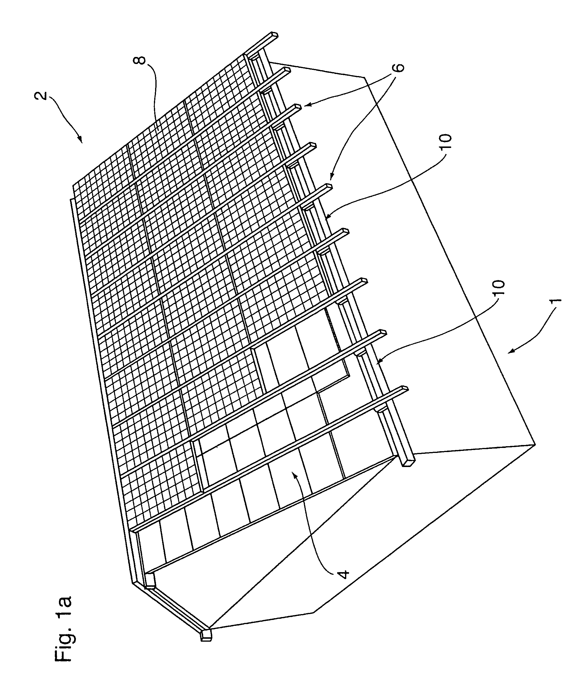
[0025]FIG. 1a is a schematic showing a building 1 with a solar panel roof surface 2 that in the northern hemisphere is generally south facing. The solar panel roof surface is supported by roof substructure 4 that includes a series of parallel hollow support beams 6. A series of solar panels 8 are supported above the roof support substructure 4 and these panels receive solar radiation and produce electrical power. As shown in FIG. 1a, the individual solar panels 8 are each supported between a pair of adjacent parallel hollow support beams 6 and the panels are placed in end to end abutment to form elongate segments of abutting panels shown as 10.

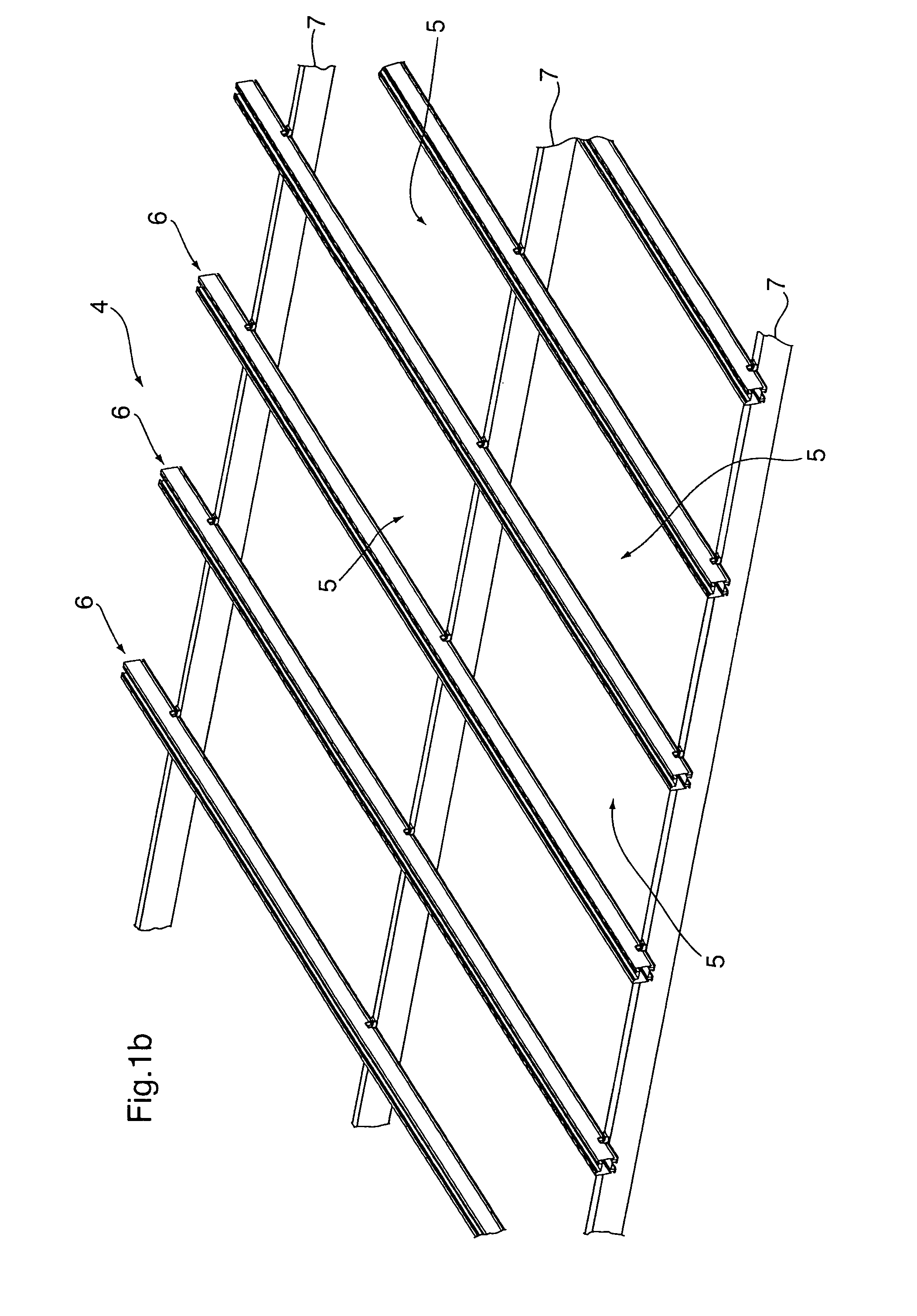
[0026]Additional details of the roof support substructure 4 are shown in FIG. 1b, FIG. 2 and FIG. 5. The series of parallel hollow support beams 6 are immediately below the solar panels and provide the direct support for the panels. The series of parallel hollow support beams 6 can be supported by a series of appropriate joists 7 as shown in F...


PUM


Abstract

A solar panel roof surface effectively uses solar panels supported by an open roof support substructure having a series of parallel hollow support beams. These hollow beams support the solar panels on a top surface and accommodate drainage along the beams. The solar panels are secured to an upper surface of the hollow support beams and in combination therewith define a closed sloped roof surface. The series of solar panels are positioned on the beams to define elongate segments of abutting panels. The abutting panels include a sealing arrangement between panels to allow flow of water along the length of the elongate segments. The hollow support beams include a top surface with a central securing slot positioned between panel segments and panel segment support surfaces either side of said securing slot for supporting edges of the solar panels. Fasteners engage the securing slot and the upper edge of the panels to secure the panels to the upper surface of the support beams.

Description

FIELD OF THE INVENTION[0001]The present invention relates to solar panel roof surfaces, and in particular to a roof system where the solar panels cooperate with the roof support substructure to define in combination a closed sloped roof surface. In contrast to roof mounted solar panel systems, the solar panels of the present system form part of the actual roof structure.BACKGROUND OF THE INVENTION[0002]Solar panel systems are primarily arranged on existing roof surfaces that are oriented to the south and slanted or sloped. The actual solar panels are mounted on beams that overly an existing roof covering. The solar panel systems do not provide a roof cover that fulfills the function of protecting against the wind and directing rain and other moisture off the roof.[0003]The solar panel roof surface of the present invention is defined by a roof support substructure essentially comprising support beams with solar panels attached to the support beams and providing the actual roof functi...

Claims


Application Information

Patent Timeline
Patent Type & Authority Patents(United States)
IPC IPC(8): E04D13/18E04D1/30
CPCF24J2/045F24J2/4614F24J2/465F24J2/5205F24J2/5211H02S20/23H02S20/00F24J2002/5215Y02B10/12Y02B10/20Y02E10/44Y02E10/47Y02E10/50F24J2002/5226F24S80/70F24S20/67F24S25/20F24S2025/807F24S25/33F24S2025/801F24S25/636F24S40/44Y02B10/10
Inventor SCHOELL, GEORGE
Owner 2192780 ONTARIO OA GALAXY ENERGY AMERICAS
Why Eureka
Eureka Blog
Learn More