Device for frontal termination of a floor covering

a technology for floating floors and devices, applied in the direction of treads, structural elements, building components, etc., can solve the problems of hardly being performed with the needed narrow manufacturing tolerance, and the need for acceptance of edge elevation

Inactive Publication Date: 2012-09-18
NEUHOFER JR FRANZ
View PDF24 Cites 14 Cited by
  • Summary
  • Abstract
  • Description
  • Claims
  • Application Information

AI Technical Summary

Benefits of technology

[0004]The invention is thus based on the object of designing a device of the type described at the beginning for the frontal termination of a floor covering in such a manner that an at least essentially continuous transition from the floor covering to the terminus profile is possible, without having to provide a formfitting connection between the floor covering and the terminus profile.
[0010]If the stop is implemented as one of two webs of the fastener fitting resulting in a receptacle groove for a clamping web of the terminus profile, especially simple design conditions may be maintained, because the stop may also be used for a pressfit between the terminus profile and the fastener fitting. For adaptation to greater thickness differences of the laid floor coverings, the two webs of the fastener fitting forming the receptacle groove for the clamping web of the terminus profile may have intended breakpoints, not only a height adaptation of the rest for supporting the terminus profile formed by a web, but rather also an adaptation of the depth of the receptacle groove for a clamping web being made possible by the shortening of the webs connected thereto.
[0011]The rest for supporting the terminus profile may be formed by a support body separate from the fastener fitting, which is fastened to the fastener fitting, for example, with the aid of a catch connection like a snap closure. Adaptations to floor coverings of different thicknesses may also be performed easily with the aid of such separate support bodies. It is thus possible to increase the support height of the support bodies by inserts or to reduce it by prepared intended breakpoints. Especially favorable design conditions result in connection with separate support bodies for the rest of the terminus profile if the support body results in the part of a pressfit for the terminus profile associated with the fastener fitting.
[0012]A further embodiment of a rest for the terminus profile is obtained in that the rest comprises a plastic body, preferably made of hard foam, glued on one side to the fastener fitting and on the other side to the terminus profile during its curing. This plastic body may be applied to the fastener fitting before its curing and may be compressed to the support height required for the particular thickness of the floor covering with the aid of the terminus profile attached butt-jointed to the floor covering, to obtain not only a location of the terminus profile adapted precisely to the thickness of the floor covering, but rather also good fastening of the terminus profile to the fastener fitting after the curing. Plastic bodies made of hard foam are especially suitable for this purpose.
[0013]In order that the fastener fitting connected in a shear-resistant manner to the floating-laid floor covering may be prevented from lifting off of the subfloor without endangering the free movement compensation for the floor covering, the fastener fitting may have oblong holes running transversely to the front face for receiving fastener screws engaging in the subfloor. The floor covering is retained pressed against the subfloor in its edge area by this measure. The oblong holes penetrated by the fastener screws ensure the required movement play transversely to the front face of the floor covering. The terminus profile may also additionally be secured against lifting off of the subfloor if the fastener fitting has a projecting clamping web engaging in a groove of the terminus profile in the area of its longitudinal edge facing away from the front face of the floor covering. This clamping web prevents unintentional lifting off of the terminus profile from the fastener fitting, which is significant in particular if the fastener fitting is also fixed in height in relation to the subfloor with the aid of fastener screws.

Problems solved by technology

These known devices for the frontal termination of a floor covering have the disadvantage, however, that an edge elevation must necessarily be accepted due to the longitudinal edge section of the terminus profile overlapping the floor covering.
A continuous, flush attachment of the terminus profile to the floor covering is thus possible, but the formfitting attachment of the floor profile to the floor covering requires complex processing of the frontal edge areas of the floor covering, which may hardly be performed with the needed narrow manufacturing tolerance when laying a floor covering on location.

Method used


Image

  • Device for frontal termination of a floor covering
  • Device for frontal termination of a floor covering
  • Device for frontal termination of a floor covering

Examples


Embodiment Construction

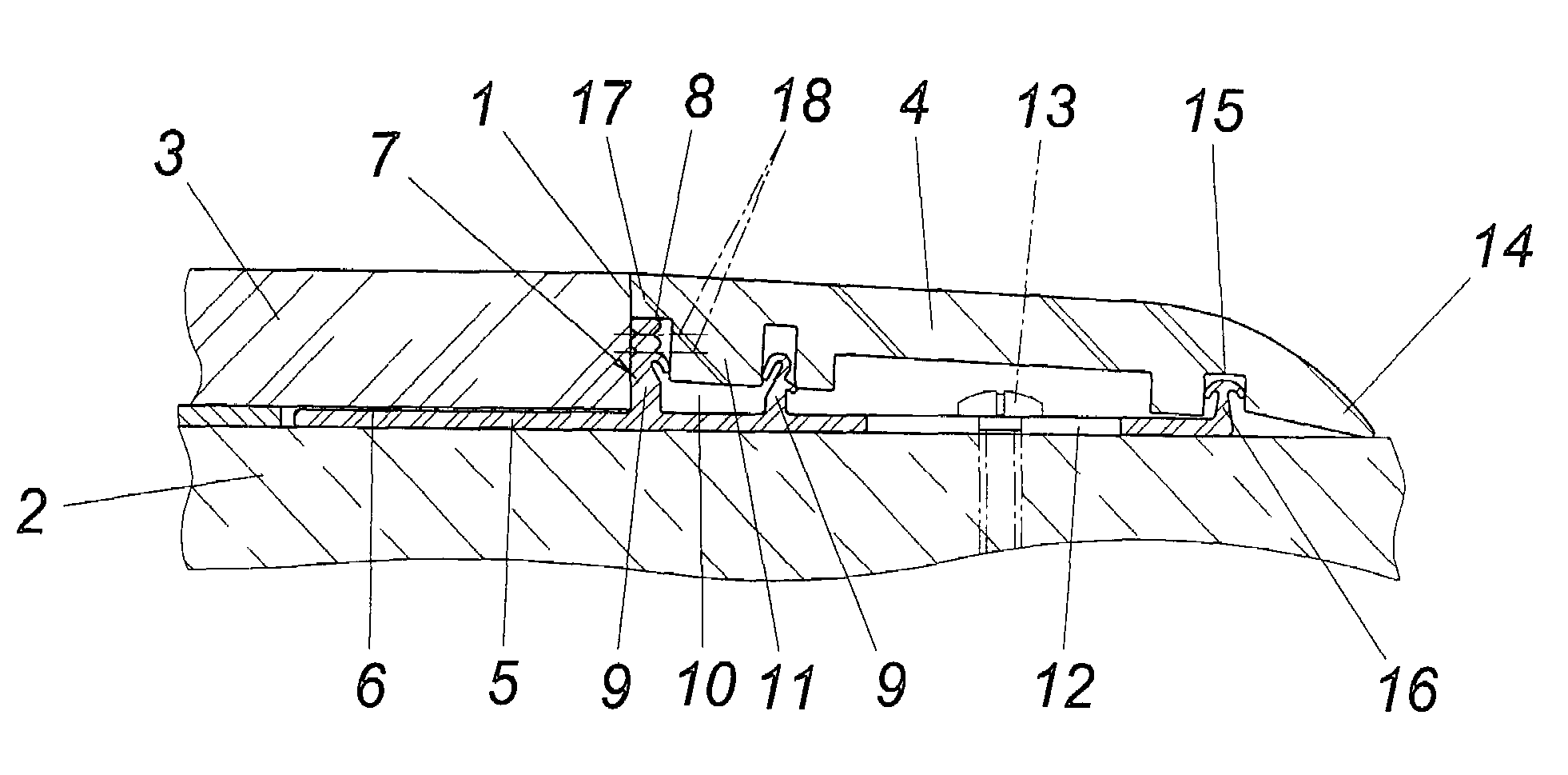
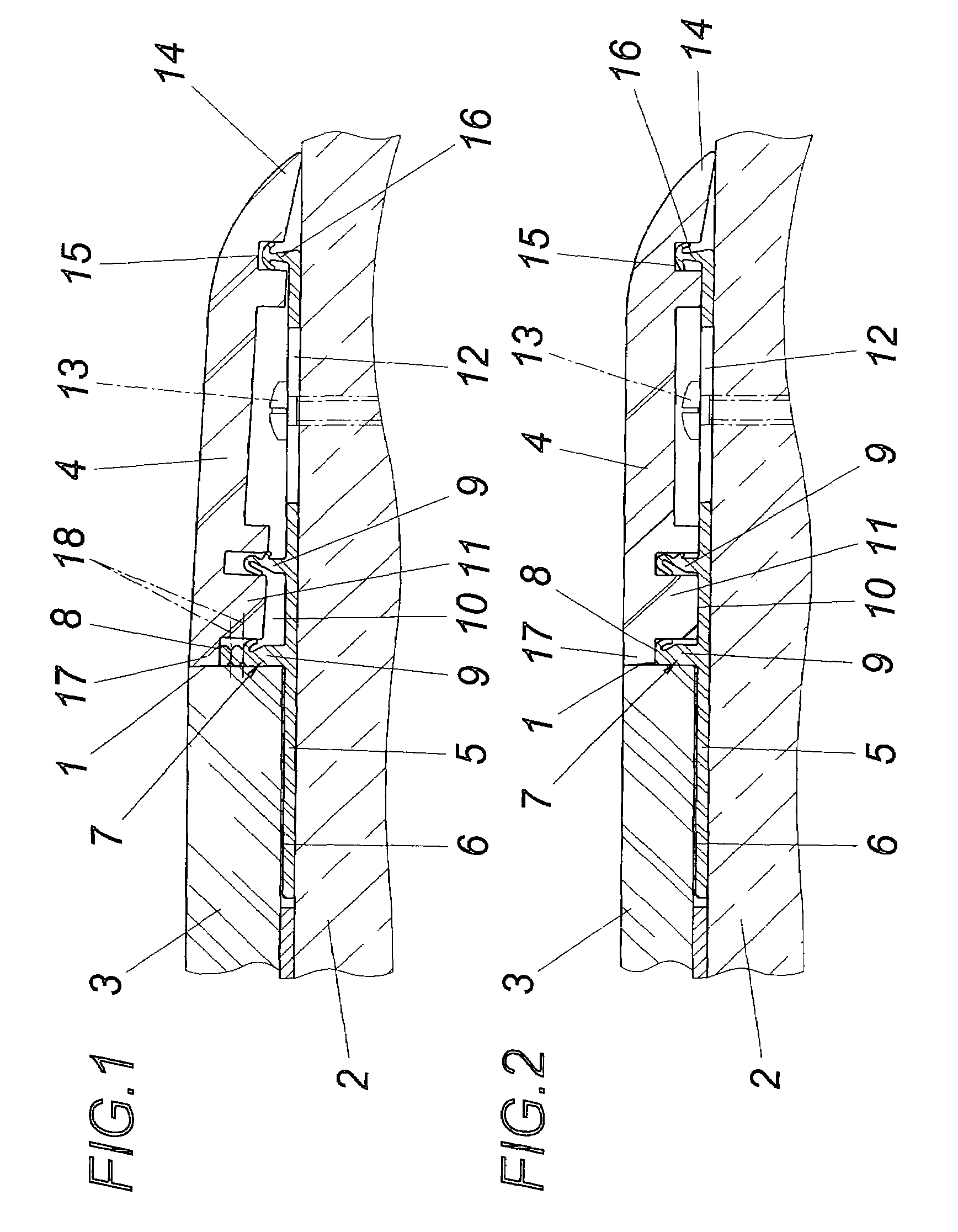
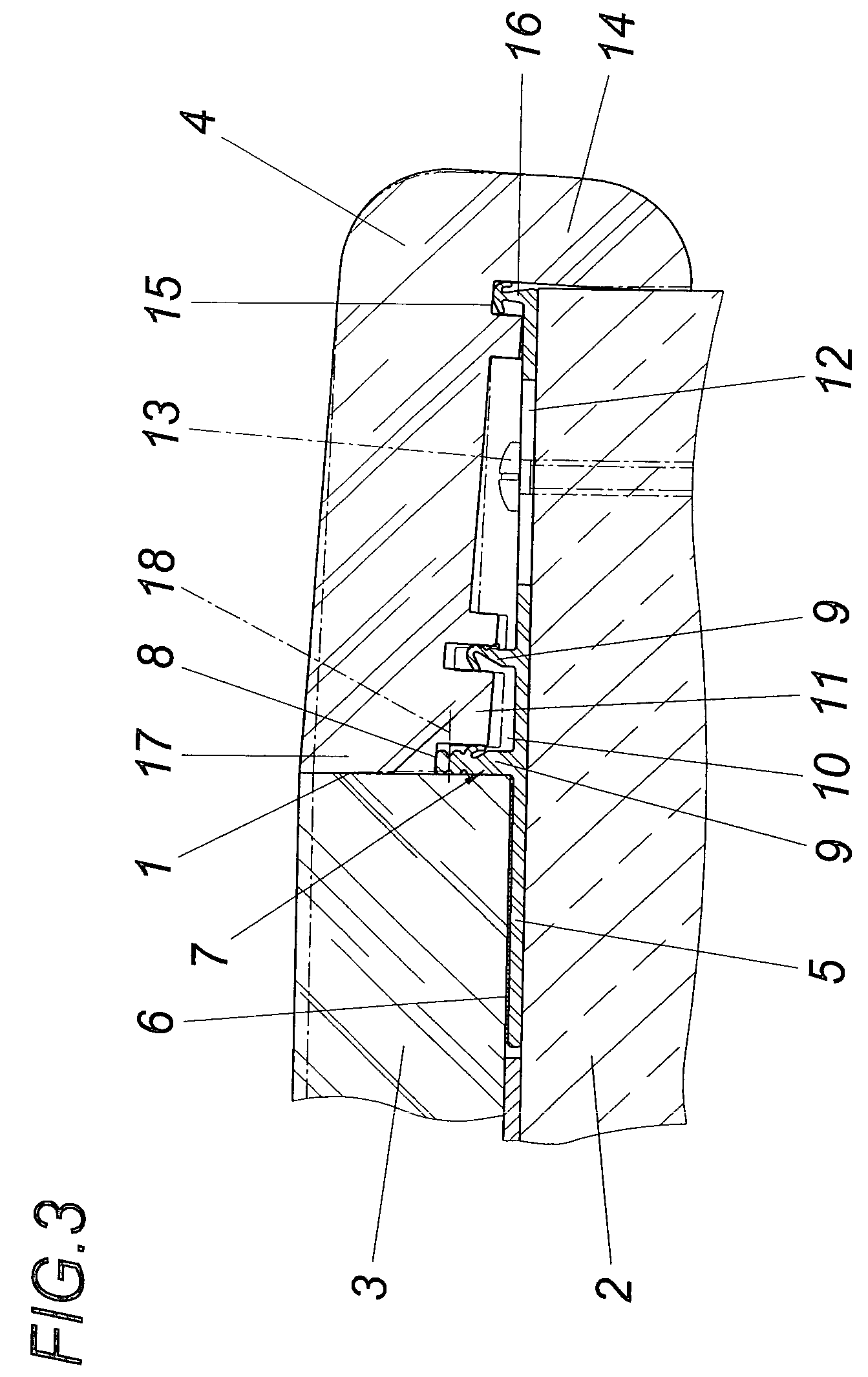
[0026]As may be seen from the exemplary embodiment in FIGS. 1 and 2, the front face 1 of a floor covering 3 laid floating on the subfloor 2 is covered with the aid of a terminus profile 4, which is retained in a fastener fitting 5. This fastener fitting 5 engages below the floor covering 3 and is connected in a shear-resistant manner to the floor covering 3 via an adhesive 6. The location of the fastener fitting 5 in relation to the front face 1 of the floor covering 3 is constructively fixed by a stop 7 for the front face 1 of the floor covering 3. This stop 7 forms a rest 8 for the terminus profile 4, which adjoins the front face 1 of the floor profile 3 butt-jointed and thus ensures a continuous transition from the floor profile 3 to the terminus profile 4, without having to additionally process the floor covering 3 in area of the front face 1.

[0027]The retention of the terminus profile 4 in the fastener fitting 5, which is implemented in the exemplary embodiment as a fastener ra...


PUM


Abstract

A device is described for the frontal termination of a floating-laid floor covering (3) having a terminus profile (4) and having a fastener fitting (5) for the terminus profile (4) resting on a subfloor (2). To provide advantageous design conditions, it is suggested that the fastener fitting (5) be connected in a shear-resistant manner to the floor covering (3) and have a rest (8) for the terminus profile (4) butt-jointed on the front face (1) of the floor covering (3).

Description

CROSS REFERENCE TO RELATED APPLICATIONS[0001]This application is the National Stage of PCT / AT2006 / 000434 filed on Oct. 24, 2006 which claims priority under 35 U.S.C. §119 of Austrian Application No. A 1727 / 2005 filed on Oct. 24, 2005. The international application under PCT article 21(2) was not published in English.FIELD OF THE INVENTION[0002]The invention relates to a device for the frontal termination of a floating-laid floor covering having a terminus profile and having a fastener fitting for the terminus profile resting on a subfloor.DESCRIPTION OF THE PRIOR ART[0003]To cover the front face of a floor covering, it is typical to provide terminus profiles, which are held on a subfloor with the aid of a fastener fitting. For this purpose, the fastener fitting, which may be implemented in the form of a fastener rail or by single fittings positioned at a distance from one another along the front face to be covered of the floor covering, forms a receptacle groove between two projecti...

Claims


Application Information

Patent Timeline
Patent Type & Authority Patents(United States)
IPC IPC(8): E04C2/38
CPCE04F19/061E04F11/166E04F19/067E04F19/066
Inventor NEUHOFER, JR., FRANZ
Owner NEUHOFER JR FRANZ
Why Eureka
Try Eureka