Pallet rack impact protector

a protection device and pallet rack technology, applied in the direction of building components, structural elements, domestic objects, etc., can solve the problems of severe safety and financial loss potential, destructive dynamic impact force between the moving mhe and the pallet rack, and the need for simultaneous use of central and peripheral vision, so as to prevent or reduce the likelihood of damage to the racking uprigh

Active Publication Date: 2012-09-18
RACK ARMOR
View PDF86 Cites 43 Cited by
  • Summary
  • Abstract
  • Description
  • Claims
  • Application Information

AI Technical Summary

Benefits of technology

[0015]One object of embodiments disclosed herein is to prevent or reduce the likelihood of damage to racking uprights.
[0016]Another object of the embodiments disclosed herein is to mitigate actual damage to racking uprights to the lowest levels so far as is reasonably practicable.
[0017]The pallet racking upright protection device according to a specific embodiment disclosed herein self attaches to the front and lateral sides of an aisle facing rack upright. The composite protection device constitutes two or more major components. An outer component is made from a resilient elastomeric polymer based material that is semi tubular in shape. This outer component serves to deflect and diffuse kinetic energy of motion so as to prevent or minimize impact damage to the upright and the frame's components therein. An internal component of the protection device is made from a relatively less dense elastomeric material. This internal component is synergistic in form and function to the external component, and serves to receive and absorb and further diffuse the kinetic energy of motion from impacts and to promote the repositioning of the whole device to a position similar to before the impact occurrence.
[0045]Preferably, said inner liner is configured such that, after receiving an impact, the inner liner promotes the repositioning of the whole device to a position similar to a position of the device before an impact occurred.
[0046]Preferably, said outer shell, when fitted to an upright column, having a front member and first and second side members, surrounds the front member, and partially surrounds first and second side members thereby protecting the front member and parts of the side members from direct impact and partially surrounds each of the first and second side members, and said outer shell also surrounds said inner liner, which resides, in use between a substantially part cylindrical inner surface of the outer shell, and an outer face of the front member, an outer face of the first side member and an outer face of the second side member.
[0055]an assembly of elastomeric synthetic compound components that partially encapsulate the principal elements of the vertical sections of a metal pallet rack for the purpose of preventing impact damage caused to the pallet rack by mechanical handling equipment.

Problems solved by technology

During these operations, there is a likelihood destructive dynamic impact forces between the moving MHE and the pallet racking may occur.
Lateral impacts can have severe safety and financial loss potential.
It usually occurs in a visually cluttered environment, requires the simultaneous use of central and peripheral vision and involves relatively complex MHE-control activities.
Thus, a standard visual test cannot predict how efficiently an operator can use peripheral visual information in complex tasks such as operating MHE.
It has been shown that peripheral retinal sensitivity may be impeded as the amount of information the subject is required to process mentally is increased.
As a consequence, important visual stimuli in the periphery of a person's vision may remain undetected when cognitively demanding tasks involving central vision are being performed.
Thus, the proximity of the MHE to the vulnerable lower sections of an upright section is difficult to monitor in a manner that is reasonably practicable and the risk of impacts occurring increases.
Invariably, such damage has direct costs to an organization's resources.
Warehouse maintenance may absorb an average of only five percent of total warehouse costs but any neglect of the issues can have cost consequences far beyond that fraction.
Damage to racking incurs both direct costs (e.g. component replacement and labor costs, damaged stock, damaged MHE, accidents and incidents) and indirect costs (e.g. reduced storage capacity, administration costs, employee absence, litigation, increased insurance premium, adverse publicity and overall disruption of business).
However, such column protectors require penetrating expansion bolts, which compromise the integrity of the concrete floor, and over time are subject to degrading or working loose.
Further, on impact, they are prone to buckling and bending, or the bolts are ripped out of the concrete when subject to impact from a vehicle or MHE.
They are also time consuming to replace when damaged, and replacement can be made more difficult where the bolts have sheared or bent, or have damaged the concrete floor.
However, this type of protector is bulky because it relies on a single molded piece to absorb all impact forces, and therefore that molded piece has to be relatively thick.
With this type of know protector, serious damage to a column after an impact can go undetected because removal of the protector is not easy.
Such column protectors are inefficient at dissipated impact forces due to their shape, having outer surfaces which lie parallel to the surfaces of the underlying columns, and act to transfer impact forces undeflected, in a direction directly to the underlying columns.
They also suffer from the problem of splitting at their edges when subjected to impact.
Additionally, their removal and replacement generally requires tools and new wires, ties or straps to attach the protector to the racking column upright, which in turns dissuades inspection of the parts of the column which are hidden from view by the protectors.
Significant damage to the hidden parts of the columns can go undetected.

Method used


Image

  • Pallet rack impact protector
  • Pallet rack impact protector
  • Pallet rack impact protector

Examples


first embodiment

[0097]

Outer shell:Height:59 cm ±5 mm.Diameter:10.7 cm ±2 mmWall thickness:7 mm ±1.5 mmCut away angle:85°±5°Circumference around 27.3 cm ±5 mmouter shell between longitudinal edges:Inner liner:Height:59 cm ±5 mm.Diameter:9 cm ±1 mm“U” channel width:7.8 cm ±2 mm“U” channel depth:2.6 cm ±2 mmMax. distance “U” channel 3.6 cm ±2 mmsurface to outer surface:

second embodiment

[0098]

Outer shell:Height:60 cm ±5 mm.Diameter:12.5 cm ±2 mmWall thickness:8 mm ±0.5 mmCut away angle:90°±5°Circumference around outer shell28.8 cm ±5 mmbetween longitudinal edges:Inner liner:Height:59 cm ±5 mm.Diameter:10.6 cm ±1 mm“U” channel width:9.0 cm ±5 mm“U” channel depth:1.4 cm ±7 mmMax. distance “U” channel 3.0 cm ±4 mmsurface to outer surface:

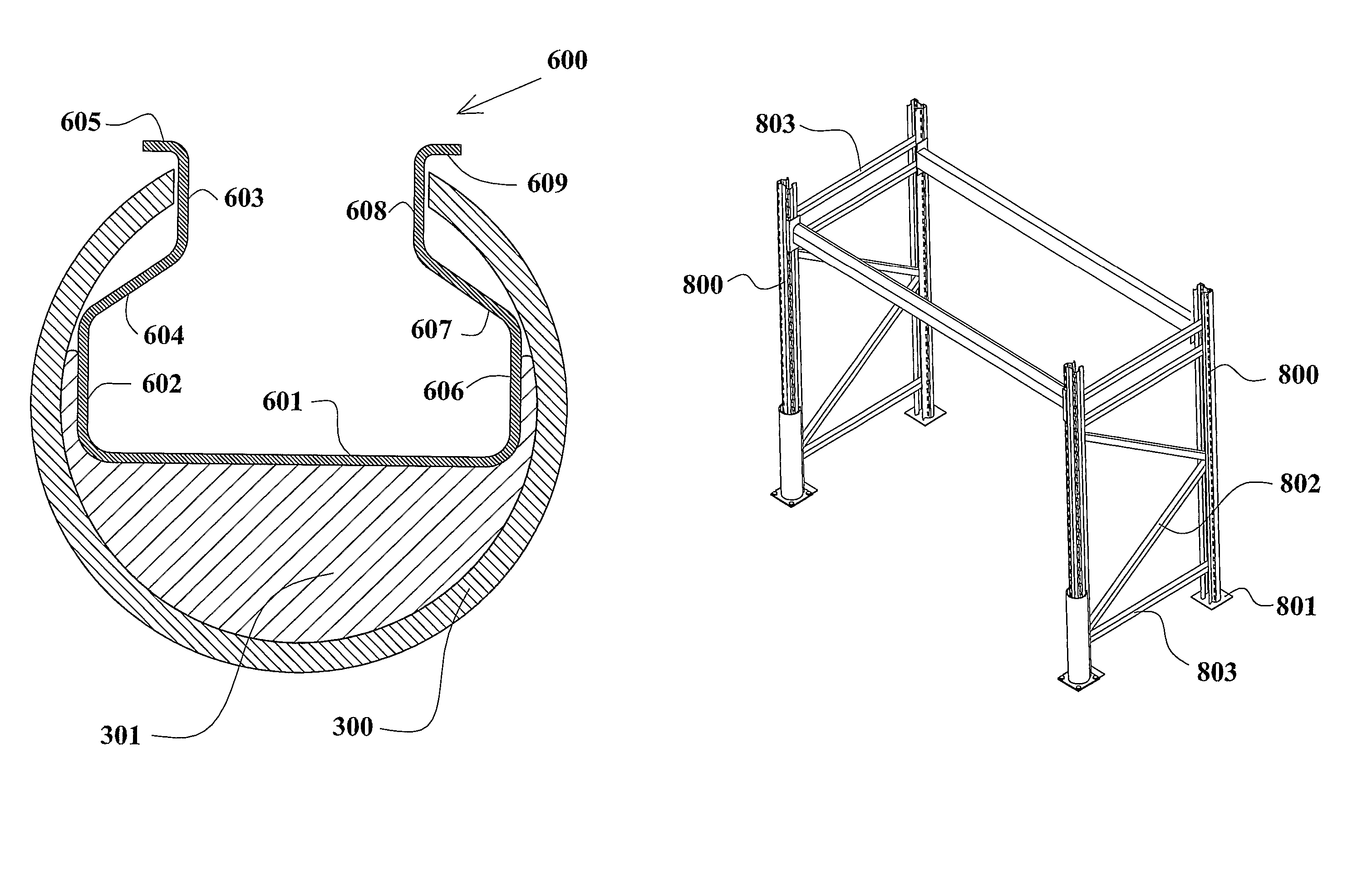
[0099]Referring to FIG. 6 herein, there is illustrated schematically in cut away cross section from above, a column post 600 of a racking system, having the column protector device installed. The known post comprises an elongate metal member 600 which is channel shaped in cross section, and presenting a substantially rectangular front aspect, the member comprising a front member 601; a first outer side member 602 connected to the front member 601 at one edge thereof and extending laterally from the front member; a first inner side member 603 disposed inwardly of the first outer side member 602, and extending approximately parallel the...


PUM


Abstract

A pallet rack upright column protection device for the use in preventing and reducing destructive levels of kinetic energy of motion from occurring to a pallet rack upright. The device is made from an assembly of multilateral polymer based elastomeric materials that has a primary external component, and with a synergistic less dense internal component. The device attaches directly to the front and lateral sides of the lower section of a rack upright.

Description

FIELD OF THE INVENTION[0001]The present invention relates to an impact protection device for a racking installation.BACKGROUND OF THE INVENTION[0002]The logistics of bulk storage and transport of goods and materials require an effective and efficient use of storage space. Known pallet racking offers the ability to store items using ever increasing capacities of vertical space up to the height and depth of the racks own dimensions. Adjustable pallet racking (APR) is the most common type of pallet racking system in use throughout the world. APR is a skeletal system of vertical, diagonal and horizontal interconnecting steel members. APR installations are usually constructed with a one pallet deep run of racking on either side of an operating aisle. If the racks can only be accessed from one side only by Mechanical handling equipment (MHE) then this is called a single entry run. If the racks can be accessed from both sides then this is called a double entry run.[0003]Referring to FIG. 1...

Claims


Application Information

Patent Timeline
Patent Type & Authority Patents(United States)
IPC IPC(8): E04C3/30A47B96/14B65G1/02E01F15/04E01F15/14E04H12/22
CPCA47B95/043E01F15/141B65G1/02B65G2207/40E01F15/0469A47B96/14E01F15/14
Inventor THELWELL, GORDON
Owner RACK ARMOR
Why Eureka
Try Eureka