Closed IDC terminal

a terminal and closed technology, applied in the direction of fastening/insulating connecting parts, securing/insulating coupling contact members, electrical equipment, etc., can solve the problems of pre-stripped wire and terminal deformation, crimping technology, and correct positioning hammering, etc., to reduce production costs, reduce production costs, and the effect of constant thickness

Inactive Publication Date: 2012-09-18
TYCO ELECTRONICS BRASIL
View PDF15 Cites 11 Cited by
  • Summary
  • Abstract
  • Description
  • Claims
  • Application Information

AI Technical Summary

Benefits of technology

[0017]The purpose of the present invention is to provide an efficient connection between cables and magnetic wires, where there is no loosening at the connection point that would cause a failure of the normal contact power.
[0018]Additionally, another purpose of the present invention is to provide a terminal with a single thickness in order to reduce production costs.
[0019]A further purpose of the combination for establishing electrical contact of the present invention is to provide a metallic terminal that allows contact between the magnetic wire and the isolated cable, without the need for crimping. The terminal has two channels for inserting the wires. The channel relating to the multi-wire cable is closed, which prevents loosening caused by stress, and failure in the normal connection power. Accordingly, the terminal does not need to be made of thick material, but can be entirely made of a thinner raw material, such as that used in the part destined for the magnetic wire. This feature means the product can be manufactured with a constant thickness, thus reducing the end cost.
[0023]The channels relating to the multi-wire cable are closed, preventing wear and tear caused by inserting the thick cables and constant pressure exerted thereon. Moreover, a thinner raw material can be used in the entire terminal.

Problems solved by technology

Additionally, said device has certain limitations, since the multi-wire cables must be placed in a specific position, which may hamper the correct positioning thereof.
Another disadvantage of terminals that use crimping technology arises from the fact that the pre-stripped wire and the terminal are deformed when high pressure is exerted thereon.
This strains the terminal, and may lead to a permanent deformation of the opening, consequently generating deficiencies in the electrical conductivity.
The use of this double-thickness premilled raw material results in increased production difficulty and higher costs for the end product.
Thus, the terminal has the same disadvantages as those mentioned above, such as the increase of channel width owing to the high mechanical tension needed to remove the isolation layer of the cable at the open end, resulting in deficiencies in electrical conductivity.

Method used


Image

  • Closed IDC terminal
  • Closed IDC terminal
  • Closed IDC terminal

Examples


second embodiment

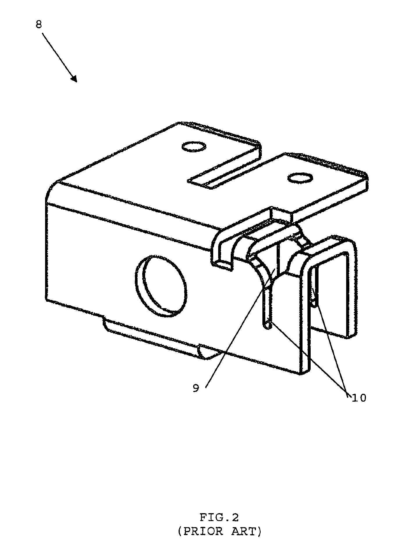
[0050]FIG. 2 is the metallic terminal of the prior art. In this terminal 8, two openings 9 and two channels 10 to receive the multi-wire cable are arranged parallel, wherein one of the channels is slightly wider than the other. The purpose of this difference in width is to absorb vibrations as may occur in the equipment wherein it is installed, preventing vibration from interfering at the point of electrical contact of the terminal.

first embodiment

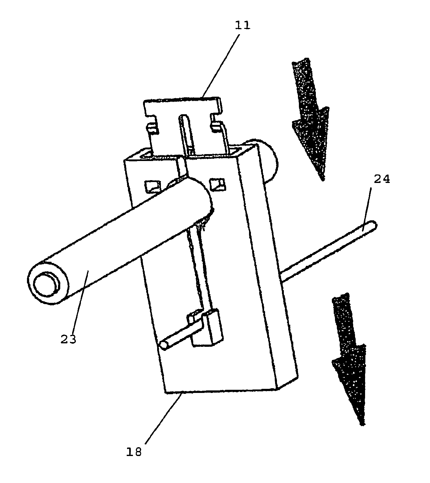
[0051]FIGS. 3 to 11 present the terminal and casing combination of the present invention in a

[0052]As can be seen in FIGS. 3, 4 and 5 of the drawings, the terminal 11 of the present invention comprises a hole 12 for inserting the multi-wire cable and a closed channel 13 linked to said hole 12.

[0053]Additionally, the terminal has an opening 14 linked to a slot 15 for inserting the magnetic wire.

[0054]In order to avoid displacement of the terminal inside the casing, which could compromise the electrical contact, said terminal has projections 16 to be fitted into the casing. Said projections serve as an anchor for the terminal in the casing, acting by interference. Inserting the terminal in the casing will cause the projections to drive into the plastic part of the casing. Additionally, the terminal optionally has flaps 17 to be fitted into the casing, avoiding movement that might compromise the electrical contact.

[0055]FIGS. 6, 7 and 8 present an arrangement of the casing 18 of the pr...


PUM


Abstract

This present invention refers to a combined terminal and casing for establishing electrical contact between a multi-wire cable and a magnetic wire that uses the insulation displacement connector (IDC) concept, wherein the terminal (11, 25) has holes (12, 26) and closed channels (13, 27) to receive the multi-wire cable (23, 36) and openings (14, 28) to receive the magnetic wire (24, 37) linked to narrow slots (15, 29). The casing (18, 31) has through-holes (20, 21, 32, 34) for inserting the multi-wire cable (23, 36) and the magnetic wire (24, 37), as well as an opening (19, 35) to receive the terminal. Inserting the terminal into the casing causes the pressure exerted on the multi-wire cable and the magnetic wire to force the entry thereof into the narrow channels, causing the isolation layer to be withdrawn, providing electrical contact between the multi-wire cable and the terminal, between the magnetic wire and the terminal and, consequently, between the multi-wire cable and the magnetic wire.

Description

CROSS-REFERENCE TO RELATED APPLICATIONS[0001]This application claims the benefit of the filing date under 35 U.S.C. §120 of International Patent Application No. PCT / BR2007 / 000154 filed Jun. 14, 2007, which claims the priority of Brazil Patent Application No. PI0602294-4 filed Jun. 14, 2006.FIELD OF THE INVENTION[0002]The present invention refers to interfaces providing electrical contact between magnetic wires and multi-wire isolated cables for use in electro-electronic equipment, such as universal engines and lamp reactors.BACKGROUND OF THE ART[0003]In order to function, electronic equipment generally needs electrical contact between wires and cables in order to propagate electrical power.[0004]For example, engine windings, bobbins, transformers and power generators use metallic terminals to establish an electrical contact between two wires, enabling the propagation of electric power among the various wires and cables of which the device is comprised.[0005]Currently, this contact c...

Claims


Application Information

Patent Timeline
Patent Type & Authority Patents(United States)
IPC IPC(8): H01R4/24
CPCH01R4/2425H01R4/245H01R11/09H01R4/2429H01R13/41
Inventor ROOSDORP, JOANNES WILLEM MARIACANTERI, HENRY CHARLES
Owner TYCO ELECTRONICS BRASIL
Why Eureka
Try Eureka