Device for connecting two electrical conductors

Inactive Publication Date: 2012-09-18
NEXANS
View PDF7 Cites 9 Cited by
  • Summary
  • Abstract
  • Description
  • Claims
  • Application Information

AI Technical Summary

Benefits of technology

[0014]Due to the preferred conical shape of the tip and a low friction of its threads, the produced contact force is high and a permanently current-conducting contact is effected between the end faces of the two conductors and the tip. If the tip is preferably composed. of the same or a similar material as that of the conductors, the current flow between the two conductors is improved. Suitable materials are copper or aluminum and an aluminum alloy or brass.

Problems solved by technology

This may lead to problems when connecting multiple-wire conductors with large cross-sections or in segmented conductors, so called “Milliken” conductors.
When the contact of the individual wires in the interior of the conductor is insufficient, heating occurs which is above average.
The electrical connection between the conductors becomes then useless relatively quickly.

Method used


Image

  • Device for connecting two electrical conductors
  • Device for connecting two electrical conductors
  • Device for connecting two electrical conductors

Examples


Embodiment Construction

[0024]In the drawings, all screws are illustrated as shearing screws whose heads are sheared off after reaching the desired tight seat of the screws at the conductors. However, it is also possible to use for the device according to the invention normal, non-shearing screws.

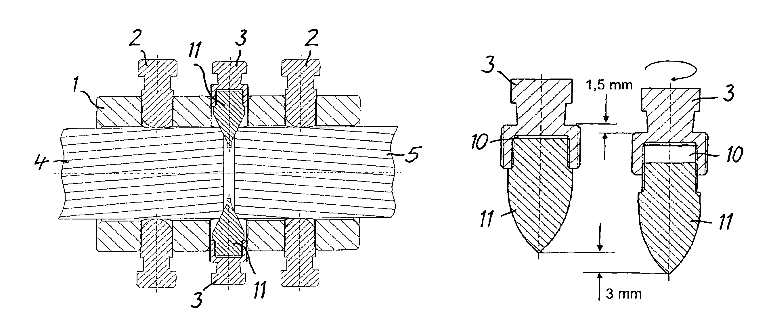
[0025]The tip rotabably arranged in the fixing screw is supposed to narrow in the direction of its free end face and constructed preferably conically. However, for simplicity's sake, it is in the following merely referred to as tip.

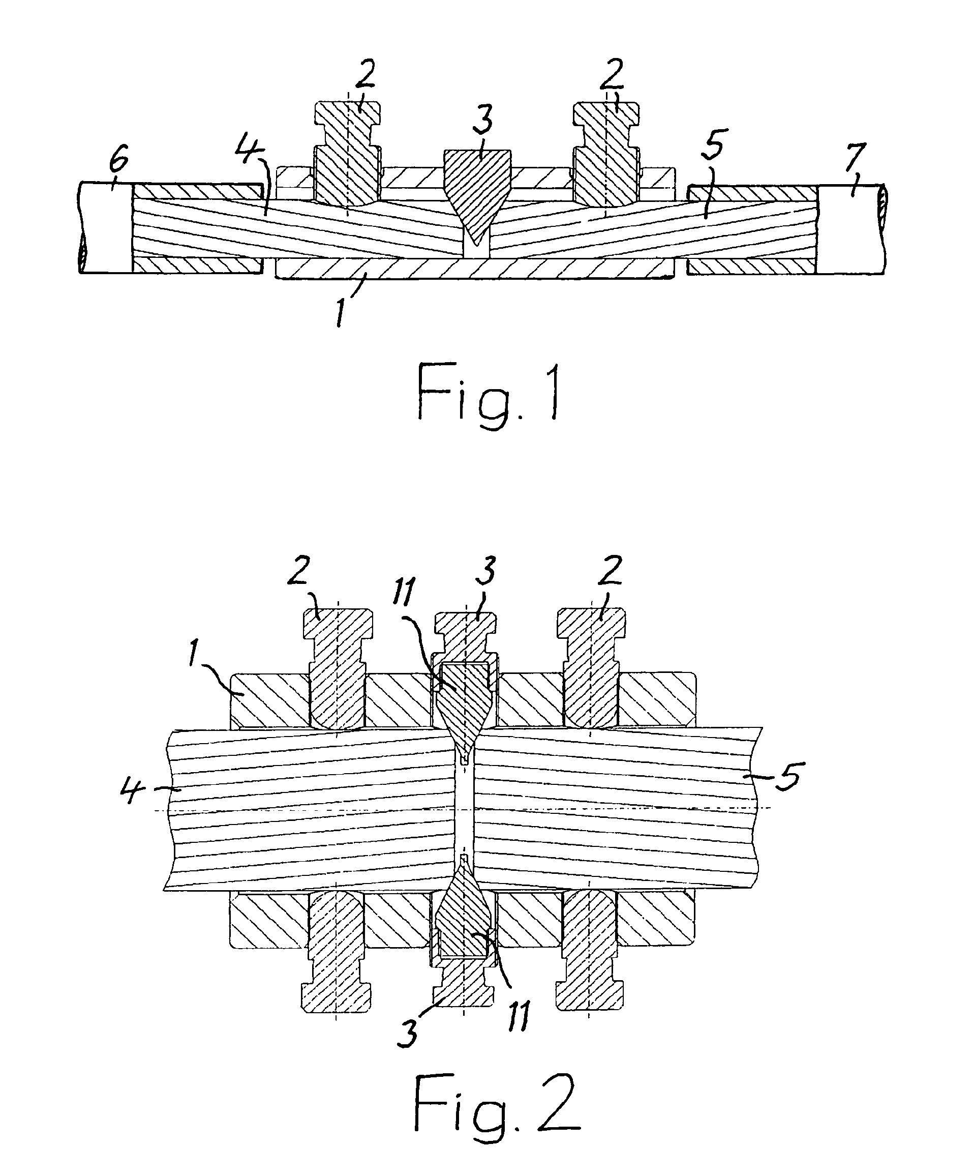
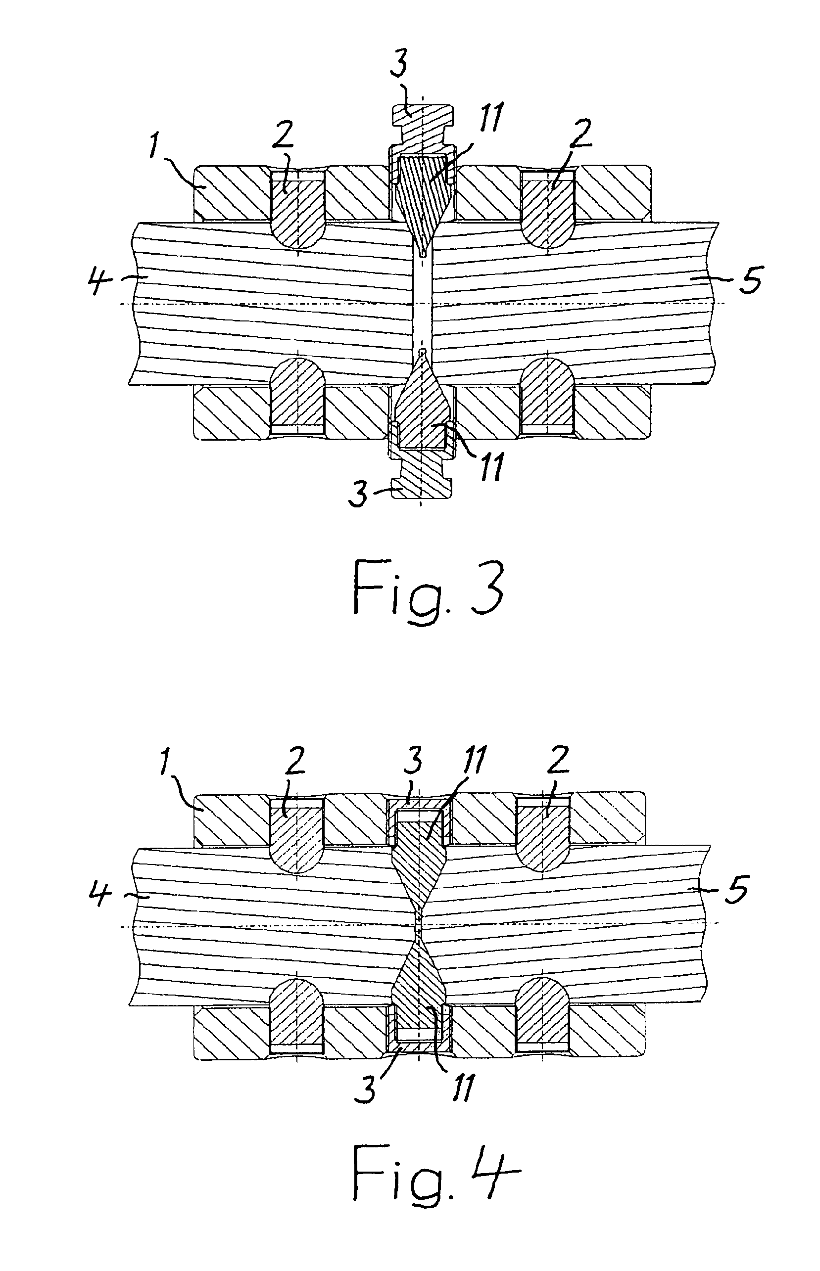
[0026]FIG. 1 shows a clamp which is composed of a galvanized aluminum alloy and is constructed of a pipe piece. The clamp 1 has three throughholes each provided with a thread in which a screw each provided with an external thread is arranged. These screws are a clamping screw 2 each in the lateral throughholes and a fixing screw 3 in the middle throughhole, wherein the exact construction is shown in FIG. 5. Projecting into the clamp 1 from two different sides are the electrical conducto...


PUM


Abstract

The invention relates to a device for connecting two electrical conductors (4, 5), comprising a metallic clamp (1) that is designed as a pipe section and that comprises in the wall thereof at least two through holes provided with a thread for receiving clamping screws (2) provided with an external thread. In the pipe section of the clamp (1), at least one central through hole provided with a thread is furnished between the two through holes in order to receive a fixing screw (3) provided with an external thread, wherein the fixing screw has a tapered, approximately wedge-shaped tip (11), which, in the assembled position, lies rigidly against the end faces of the two conductors (4, 5) inserted into the pipe section. The tip (11) provided with an external thread is screwed into a hole (10) of the fixing screw (3) provided with an internal thread, and the external thread of the tip (1) runs opposite to the external thread of the fixing screw (3).

Description

RELATED APPLICATIONS[0001]This application is a National Phase application of PCT / EP2010 / 051883, filed on Feb. 16, 2010, which in turn claims the benefit of priority from European Patent Application No. 09 290 132.1, filed on Feb. 25, 2009, the entirety of which is incorporated herein by reference.BACKGROUND[0002]1. Field of the Invention[0003]The invention relates to a device for connecting two electrical conductors, composed of a metal clamp constructed from a pipe piece, wherein the clamp has in its wall at least two throughholes provided with a thread for receiving clamping screws provided with an external thread.[0004]2. Description of Related Art[0005]Devices of this type are known and available on the market. They are used, for example, for connecting the conductors of energy cables which are composed preferably of copper or aluminum. For securing and contacting the conductors in the damp, clamping screws are used which are constructed, for example, as shearing screws. The he...

Claims


Application Information

Patent Timeline
IPC IPC(8): H01R4/38
CPCH01R4/307H01R4/36
Inventor STAUCH, GERTMARKGRAF, VOLKERGROETSCH, PETER
Owner NEXANS
Why Eureka
Try Eureka