Wind energy use

a technology of wind energy and wind power, applied in the field of eco-friendly technology, can solve the problems of insufficient cheap service, relative bulky application of wind power, and insufficient use of electrical power

Active Publication Date: 2012-09-18
ABRAMOV YURI
View PDF17 Cites 8 Cited by
  • Summary
  • Abstract
  • Description
  • Claims
  • Application Information

AI Technical Summary

Benefits of technology

[0036]Accordingly, it is a principal object of the present invention to overcome the limitations of existing methods and apparatuses for extracting water from air, and to provide improved methods and apparatus for extracting water from air and for harvesting electrical energy from streaming flow.
[0037]It is a further object of the present invention to provide methods and apparatus for more reliable water harvesting.
[0038]It is still a further object of the present invention to provide methods and apparatus for ecologically clean harvesting of water, where the forced water condensation from humid air is accomplished by an engine powered by natural wind.

Problems solved by technology

Today wind power is widely used for the electricity generation; however relatively bulky wind turbines are applied to satisfy the requirements in electrical power.
In fact, the use of the bulky wind turbines to convert the kinetic power of natural air wind inertia into electrical power does not provide a cheap enough service.
An exemplary situation is when a massive forest fire needs to be extinguished, and typically great expense is incurred for an airplane to supply an enormous amount of water to the scene of action.
On the other hand, normally, the system occupies a big area in an open space, where natural dust always covers the plates, thereby reducing the efficiency of solar energy collection.
Sometimes an effect of air saturated with water is unwanted, as for example, in plant growing incubators, where a desired high air temperature results in unwanted air saturation.
In both of the above approaches there is a need for energy consumption and mechanisms comprising moving parts, thereby requiring a degree of maintenance of the systems.
This makes the water harvesting neither reliable nor inexpensive.
Moreover, the fuel or electrical energy consumption renders these prior art methods unclean ecologically.
However, such slow convection does not allow for producing industrial amounts of water.
The pre-heated aerosols and / or dew drops subsequently evaporate back to gaseous form, thereby slowing down the desired condensation process.
But a blowing through a tiny hole between folded lips is substantially inefficient for the moisturizing.
This shock wave is not caused by wing vibration, but it is at the expense of the internal energy of the air flow, that results in an air temperature shock decrease and thereby, provokes the process of vapor condensation into water-aerosols.
A tornado is not necessarily visible; however, the intense low pressure, caused by the high wind speeds and rapid rotation, usually causes water-vapor in the air to condense into a visible condensation funnel.
On the other hand, the above-mentioned use of wind power for producing electricity is based on methods for converting the energy of the wind inertia into electricity and ignores methods for substantial conversion of the internal heat energy of naturally warm air wind into electricity.
However, it is problematic to accelerate an air flow substantially for at least the two following reasons.
First, the long streaming path causes essential skin-friction resistance.
And second, undesired drag is expected because the stream is subjected to re-direction several times.
Furthermore, nowadays use of streaming water power for producing electricity is based on methods for converting the energy of the falling water gravitationally accelerated inertia into electricity and ignores methods for substantial conversion of the internal heat energy of naturally warm water into electricity, and so, in particular, it is problematical to produce sufficient amount of electrical power from relatively slow streaming off-shore sea-water waves.

Method used


Image

  • Wind energy use
  • Wind energy use
  • Wind energy use

Examples


Embodiment Construction

[0089]The principles and operation of a method and an apparatus according to the present invention may be better understood with reference to the drawings and the accompanying description, it being understood that these drawings are given for illustrative purposes only and are not meant to be limiting.

[0090]FIG. 4 is a schematic representation of a trivial passive catcher 40 of water aerosols. Catcher 40 has plates 41 for accumulation of naturally condensed dew. The plates 41 have length L 45, width w 46 and are spaced at intervals 42. The total height of passive catcher 40 is h 47. When catcher 40 is placed in an open space, humid windy air 43 crosses though the free space intervals 42 between plates 41. If weather conditions are such that humid windy air 43 comprises water aerosols, drops of dew arise on the surfaces of plates 41. The condition occurs when the air temperature falls below the “dew-point” temperature.

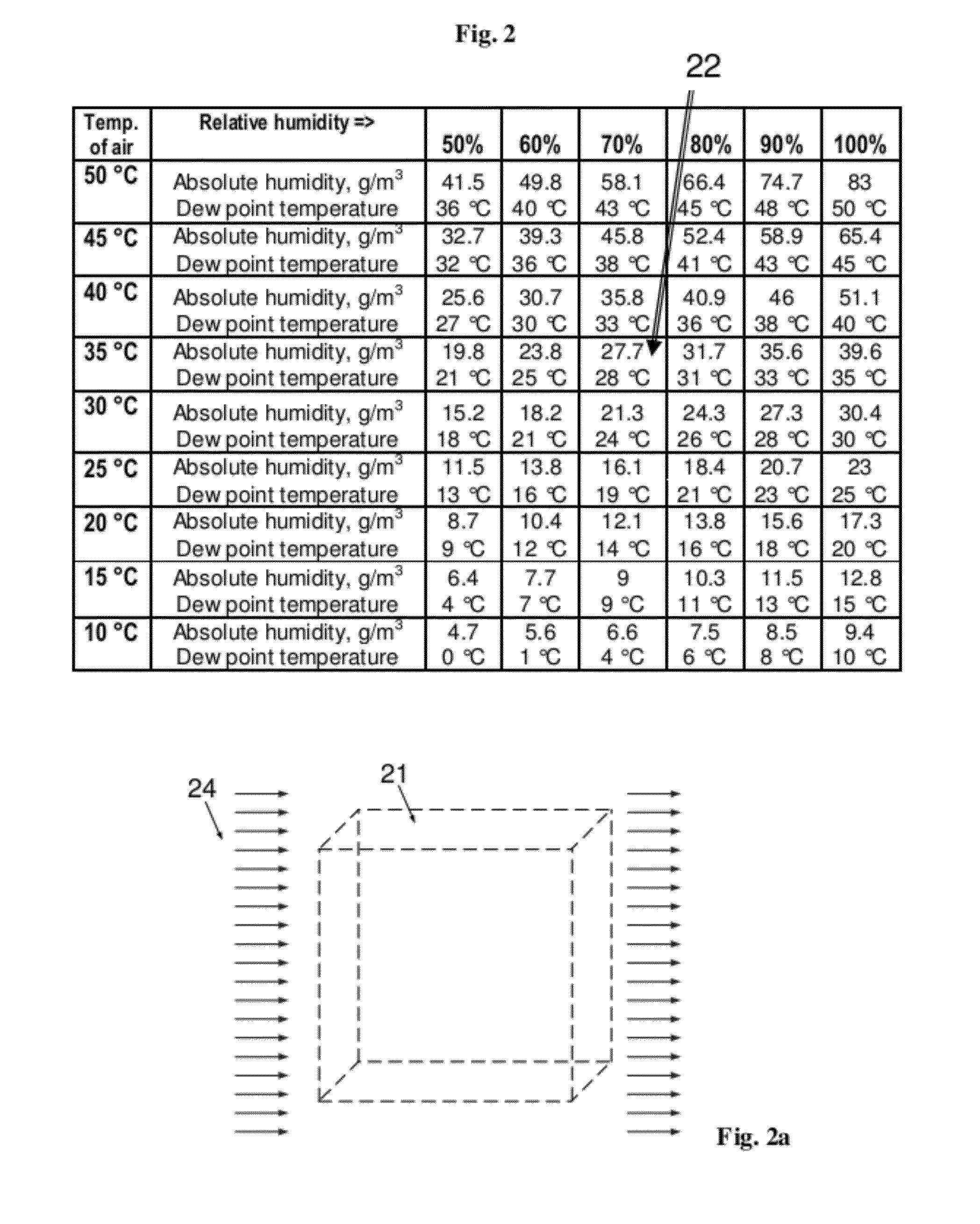
[0091]For example, referring back to prior art FIG. 2, considering...


PUM

PropertyMeasurementUnit
temperatureaaaaaaaaaa
absolute humidityaaaaaaaaaa
temperatureaaaaaaaaaa

Abstract

The invention provides wind energy use. One application provides wind energy use for water harvesting from natural humid air. The method is based on changing thermodynamic state parameters of ambient wind air portions passed through a device comprising convergent-divergent and wing-like components. Those components transform the ambient wind portions into fast and cooled outflowing air portions. A decrease in static pressure and temperature triggers condensation of water-vapor into water-aerosols. Another application of the method provides an effective mechanism for harvesting electrical energy from naturally warm air using renewable wind energy, including the wind inertia, internal heat, and potential energy stored in the air mass in the Earth's gravitational field. The electrical energy harvesting mechanism is also applicable to use of natural renewable energy of streaming water.

Description

CROSS REFERENCE TO RELATED APPLICATIONS[0001]This application is a continuation-in-part of application Ser. No. 13 / 298,678, filed Nov. 17, 2011 now abandoned, which is a continuation-in-part of (i) PCT / US / 2010 / 059,786 filed Dec. 10, 2010 and of (ii) application Ser. No. 12 / 854,196, filed Aug. 11, 2010, which is a continuation-in-part of now abandoned application Ser. No. 12 / 774,936, filed May 6, 2010 based upon and claims the benefit of U.S. Provisional Application No. 61 / 175,799 filed May 6, 2009, and U.S. Provisional Application No. 61 / 233,207 filed Aug. 12, 2009.[0002]This application is a continuation-in-part of application Ser. No. 12 / 854,196, filed Aug. 11, 2010, which is a continuation-in-part of now abandoned application Ser. No. 12 / 774,936, filed May 6, 2010 based upon and claims the benefit of U.S. Provisional Application No. 61 / 175,799 filed May 6, 2009, and U.S. Provisional Application No. 61 / 233,207 filed Aug. 12, 2009.[0003]This application is a continuation-in-part of...

Claims


Application Information

Patent Timeline
Patent Type & Authority Patents(United States)
IPC IPC(8): B01D45/00
CPCF03D1/00F05B2240/133Y02E10/725Y02E10/72
Inventor ABRAMOV, YURI
Owner ABRAMOV YURI
Why Eureka
Try Eureka