Thermoelectric module device with thin film elements and fabrication thereof

a technology of thermoelectric modules and thin film elements, which is applied in the direction of thermoelectric devices with peltier/seeback effect, thermoelectric device details, etc., can solve the problems of low efficiency of devices, low zt, and low efficiency of thin film thermoelectric materials when directly used in conventional devices

Active Publication Date: 2012-09-18
IND TECH RES INST
View PDF12 Cites 11 Cited by
  • Summary
  • Abstract
  • Description
  • Claims
  • Application Information

AI Technical Summary

Problems solved by technology

However, this device does not have high efficiency because of the limitation of the figure of merit (ZT) of bulk-shaped thermoelectric material.
However, the thin film thermoelectric material is not highly efficient when directly used in conventional devices.
Hence, the device directly applied with the thermoelectric thin film materials 216, 210 having high ZT does not perform as well as expected.

Method used


Image

  • Thermoelectric module device with thin film elements and fabrication thereof
  • Thermoelectric module device with thin film elements and fabrication thereof
  • Thermoelectric module device with thin film elements and fabrication thereof

Examples


Embodiment Construction

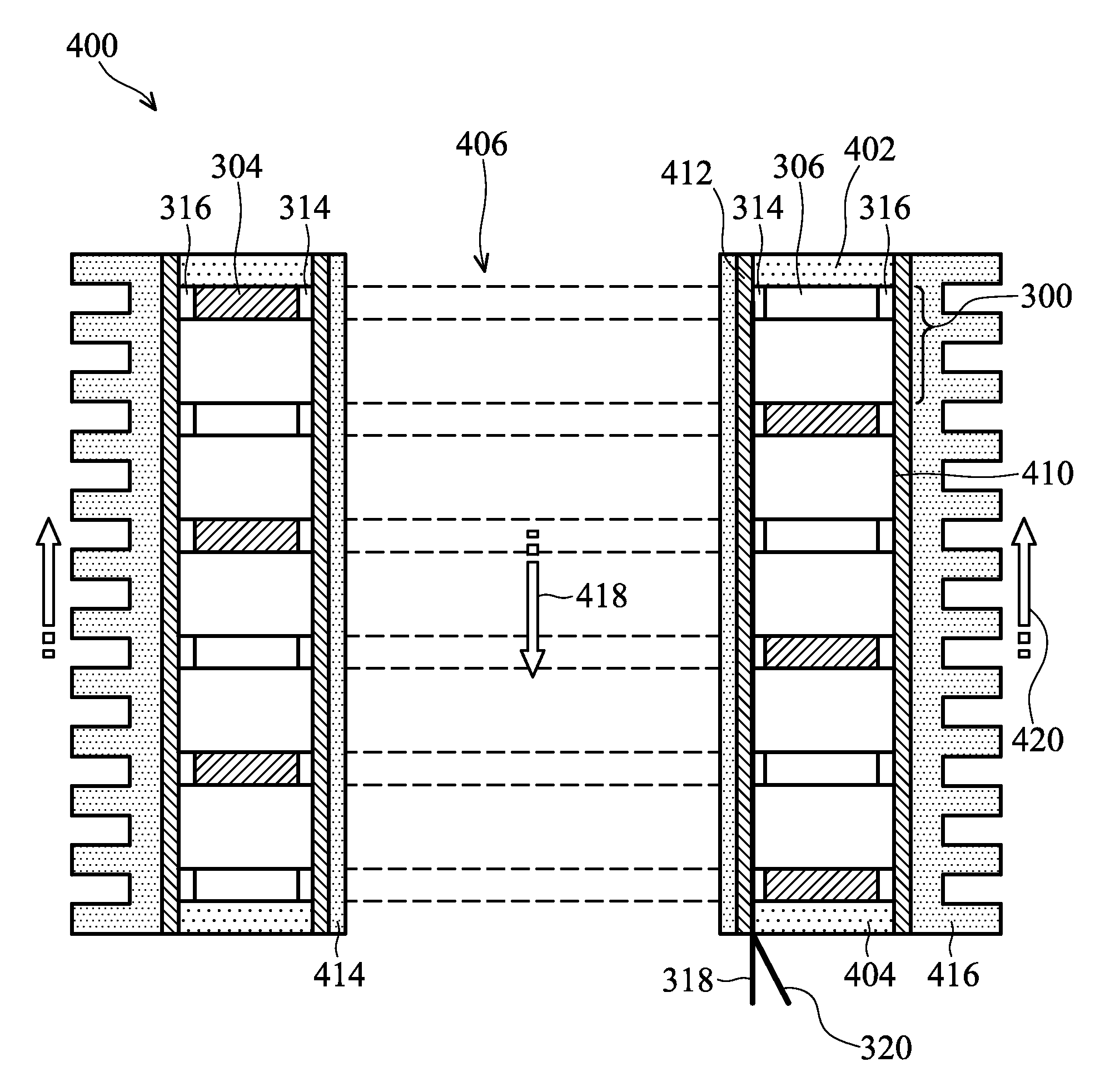
[0019]A method for forming a thin film type thermoelectric module element 300 of an embodiment of the invention is illustrated in accordance with FIG. 3A˜FIG. 6. First, referring to FIG. 3A and FIG. 3B, FIG. 3B shows a cross section along line I-I′ of FIG. 3A, a ring-shaped substrate 302 comprising an inner edge 312 and an outer edge 310. The ring-shaped substrate 302 preferably includes electrical and heat insulating material, such as ceramics with low thermal conductivity or heat resistant macromolecule material, wherein the ceramics can comprise cubic zirconia or WSe2, and the heat resistant macromolecule material can comprise polyimide. A plurality of p-type thermoelectric thin film elements (TEE) 304 and n-type thermoelectric thin film elements 306 are formed on a surface of the ring-shaped substrate 302 by, for example deposition. In the embodiment, the p-type TEE 304 and the n-type TEE 306 are about 10 nm˜200 μm thick. In addition, the p-type TEE 304 and the n-type TEE 306 of...


PUM


Abstract

A thermoelectric module device with thin film elements is disclosed. A pillar structure with a hollow region is formed by stacking a plurality of thin-film type thermoelectric module elements, each including a plurality thin-film thermoelectric pairs arranged in a ring. An insulating and thermal conducting layer covers the inner sidewalls of the hollow region of the pillar structure and the outer sidewalls of the pillar structure. A cool source and a heat source are disposed in the hollow region or outer side of the pillar structure, respectively.

Description

BACKGROUND OF THE INVENTION[0001]1. Field of the Invention[0002]The invention relates to a thermoelectric module device and fabrication thereof, and more particularly relates to a thin film thermoelectric module device.[0003]2. Description of the Related Art[0004]A thermoelectric module device is a device capable of transforming electricity into heat and / or heat into electricity, and can be applied in cooling / heating and generating electric power. When electricity is applied to a thermoelectric module device, heat absorption and heat release are generated on opposite ends of the device, thus allowing for cooling or heating. When two ends of a thermoelectric module device have temperature differences, the device can output direct current and can thus be used to generate electric power.[0005]FIG. 1 shows a cross section of a conventional thermoelectric module device. As shown in this figure, a conventional thermoelectric module device typically comprises a bulk-shaped p-type thermoele...

Claims


Application Information

Patent Timeline
Patent Type & Authority Patents(United States)
IPC IPC(8): H01L35/28H01L35/02
CPCH01L35/32H10N10/17
Inventor CHU, HSU-SHEN
Owner IND TECH RES INST
Why Eureka
Try Eureka