Method and device for carrying out a thermodynamic cyclic process

a technology of thermodynamic cycle and process, applied in the direction of machines/engines, steam engine plants, geothermal energy generation, etc., can solve the problems of unfavorable water quality and uneconomical, and achieve the effect of reducing the overall pressure level in the cycle, reducing the boiling temperature of the working medium in its turn, and increasing efficiency

Active Publication Date: 2012-09-25
KALINA POWER LTD
View PDF11 Cites 40 Cited by
  • Summary
  • Abstract
  • Description
  • Claims
  • Application Information

AI Technical Summary

Benefits of technology

[0004]For heat sources with such a low temperature a wide diversity of technologies have been developed over recent years which make it possible to convert their heat into mechanical or electrical energy with a high degree of efficiency. As well as the Rankine process with organic working media (Organic Rankine Cycle, ORC) a process known as the Kalina cycle process stands out by virtue of its markedly better levels of efficiency compared to the classic Rankine process. Various cycles for different applications have been developed on the basis of the Kalina cycle process. Instead of water these cycles use a mixture of two substances (e.g. ammonia and water) as their working medium, with the non-isothermic boiling and condensation process of the mixture being utilized to increase the efficiency of the cycle by comparison with the Rankine cycle.
[0007]Using this known cycle process as its starting point, the object of the present invention is to specify a method and a device for executing a thermodynamic cycle process, which, with the same external heat source and cooling water temperature, and with plant costs which essentially remain the same, makes it possible to produce the same or even a higher yield of mechanical and / or electrical energy, but with the method and the device standing out however by virtue of their lower complexity.
[0010]By suitably adaptating the heating surfaces of the remaining heat exchangers and other cycle parameters it is possible not only to keep the yield of mechanical and / or electrical energy the same by comparison with the known cycle but even to increase it. The costs of a possibly increased heating surface demanded in the remaining heat exchangers could in this case be largely compensated for by the omission of the second heat exchanger and the associated simplification of the pipework, thus keeping the plant costs essentially the same.
[0012]The part vaporization of the pressurized, liquid working medium flow by part condensation of the expanded working medium flow can be favorably improved by the pressure of the vaporized phase amounting to less than 24 bar and thereby being far less than the 33 bar figure known from previous cycles. In this way the overall pressure level in the cycle can be reduced, which enables the boiling temperature of the working medium in its turn to be reduced.
[0015]In accordance with an embodiment of the invention a multi-substance mixture is used as the working medium. The multi-substance mixture is preferably a two-substance mixture especially an ammonium-water mixture. As a result of the non-isothermic vaporization and condensation of such a mixture an especially high level of efficiency of the cycle can be achieved.

Problems solved by technology

Its high boiling point however makes water unattractive, especially when using heat sources with temperatures between 100° to 200° C., e.g. geothermal liquids or waste heat from combustion processes, because the process is not cost effective.

Method used


Image

  • Method and device for carrying out a thermodynamic cyclic process
  • Method and device for carrying out a thermodynamic cyclic process
  • Method and device for carrying out a thermodynamic cyclic process

Examples


Embodiment Construction

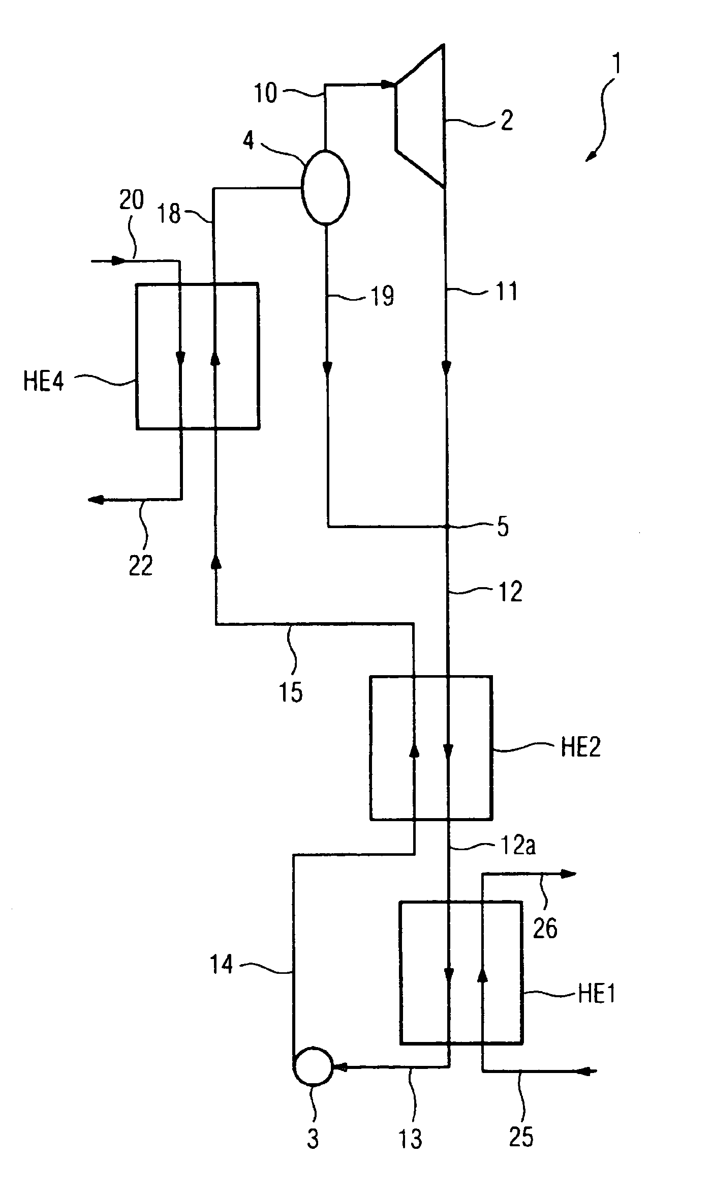
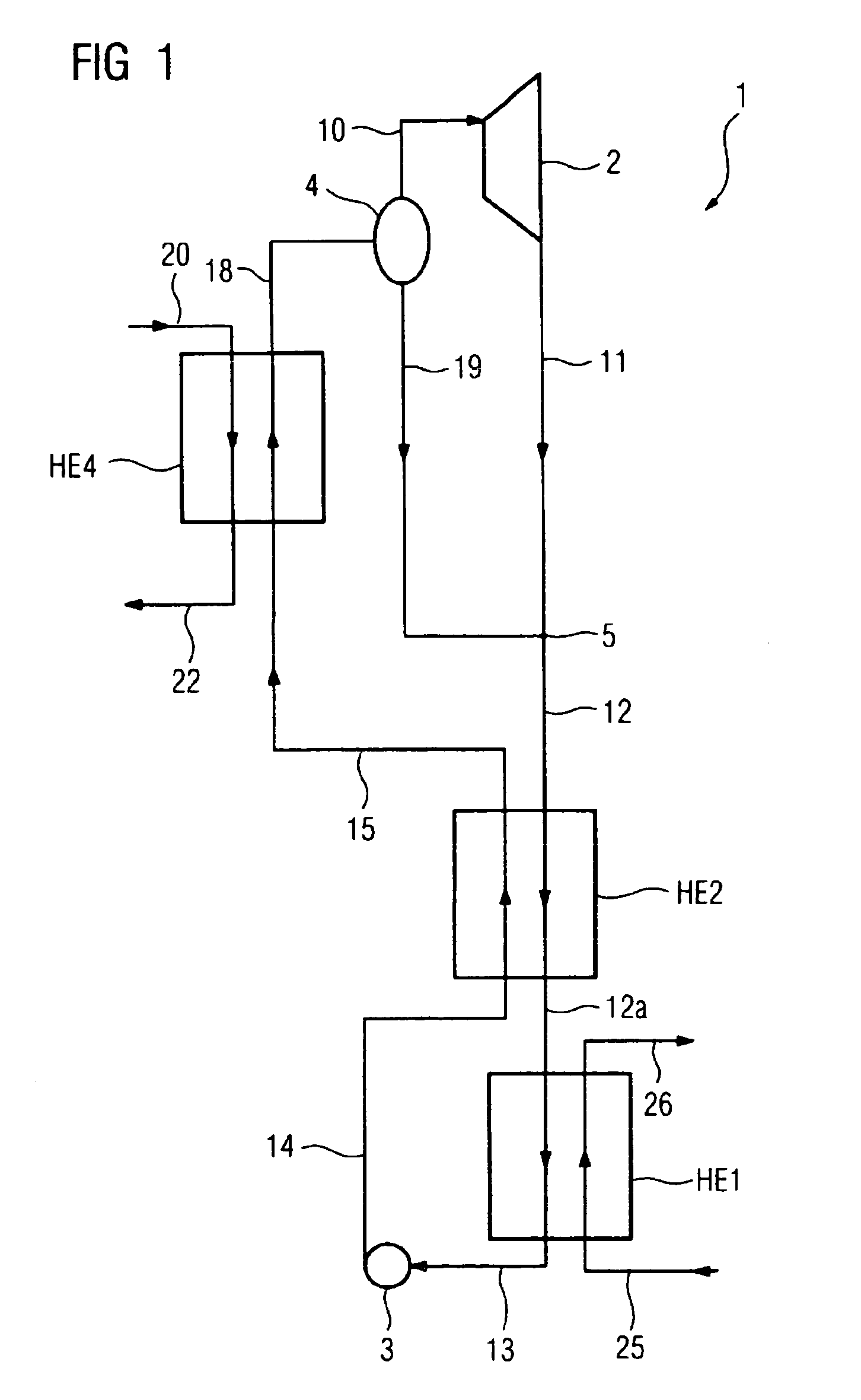
[0023]The device 1 shown in FIG. 1 for executing a thermodynamic cycle process features a (recuperative) heat exchanger HE4, which on the primary side has hot thermal water 20 from a geothermal source not shown in any greater detail flowing through it and is connected on the secondary side on the one hand to a heat exchanger HE2 and on the other hand to a separator 4. The separator 4 is used for separating a vapor phase from a liquid phase of a partly vaporized working medium. A vapor-side output of the separator 4 is connected to a turbine 2. The turbine 2 is connected on its output side to a mixer 5 which is still connected with a liquid input of the separator 4. On the output side the mixer 5 is connected to the secondary side of a (recuperative) heat exchanger HE2 which in its turn is connected to the primary side of a condenser HE1 through which cooling water flows. The condenser HE1 is connected at its primary-side output, if necessary via a condensing tank, via a pump 3 to th...


PUM


Abstract

In accordance with the invention, to reduce the complexity of a cycle process, a liquid working medium flow (13) is brought up to an increased pressure and through part condensation of an expanded working medium flow (12) a first partly vaporized working medium flow (15) is created. Through further vaporization of the first partly vaporized working medium flow (15) with heat which is transferred from an external heat source (20), a second at least partly vaporized working medium flow (18) is created. In this second at least partly vaporized working medium flow (18) the vapor phase (10) is separated from the liquid phase (10), subsequently the energy of the vapor phase (10) is converted into a usable form and an expanded vapor phase (11) created. The expanded vapor phase (11) is mixed with the liquid phase (19) and the expanded working medium flow (12) is formed. Through complete condensation of the partly condensed, expanded working medium flow (12a) the liquid working medium flow (13) is obtained in its turn.

Description

CROSS REFERENCE TO RELATED APPLICATIONS[0001]This application is the US National Stage of International Application No. PCT / EP2005 / 051617, filed Apr. 13, 2005 and claims the benefit thereof. The International Application claims the benefits of German application No. 10 2004 018 627.8, filed Apr. 16, 2004, both applications are incorporated by reference herein in their entirety.FIELD OF INVENTION[0002]The invention relates to a method and a device for executing a thermodynamic cycle process.SUMMARY OF THE INVENTION[0003]Thermal power stations use thermodynamic cycle processes for converting heat into mechanical or electrical energy. Conventional thermal power stations create the heat by burning fuel, in particular the fossil fuels coal, oil and gas. The cycle processes are operated in this case for example on the basis of the classic Rankine cycle process with water as its working medium. Its high boiling point however makes water unattractive, especially when using heat sources with...

Claims


Application Information

Patent Timeline
Patent Type & Authority Patents(United States)
IPC IPC(8): F01K25/06F01K7/00F01K25/08
CPCF01K25/065Y02E10/10
Inventor LENGERT, JORG
Owner KALINA POWER LTD
Why Eureka
Try Eureka