Magnetic head for perpendicular magnetic recording having a main pole and a shield

a perpendicular magnetic and magnetic recording technology, applied in the direction of magnetic recording heads, data recording, instruments, etc., can solve the problems of affecting the thickness of a portion affecting the quality of the main pole, so as to prevent the skew-induced problems and improve the write characteristics

Active Publication Date: 2012-09-25
HEADWAY TECH INC +1
View PDF8 Cites 16 Cited by
  • Summary
  • Abstract
  • Description
  • Claims
  • Application Information

AI Technical Summary

Benefits of technology

[0019]It is an object of the present invention to provide a magnetic head for perpendicular magnetic recording that is capable of ...

Problems solved by technology

This makes it difficult for the main pole to direct much magnetic flux to the medium facing surface, thus leading to degradation of overwrite property.
The above-described configuration, however, has a problem in that where the first slope of the main pole and the second slope of the write shield are opposed to each other over a large area with a small spacing between the first and second slopes, a large amount of magnetic flux leaks from the main pole to the write shield to cause degradation of write characteristics such as the overwrite property.
Reducing the first slope in length in the direction perpendicular to the medium facing surface, however, precludes a sufficient increase in the thickness of a portion of the main pole that is located farther from the medium facing surface than is the first slope.
This makes the main pole unable to direct much magnetic flux to the medium facing surface, and thus leads to degradation of write character...

Method used


Image

  • Magnetic head for perpendicular magnetic recording having a main pole and a shield
  • Magnetic head for perpendicular magnetic recording having a main pole and a shield
  • Magnetic head for perpendicular magnetic recording having a main pole and a shield

Examples


first embodiment

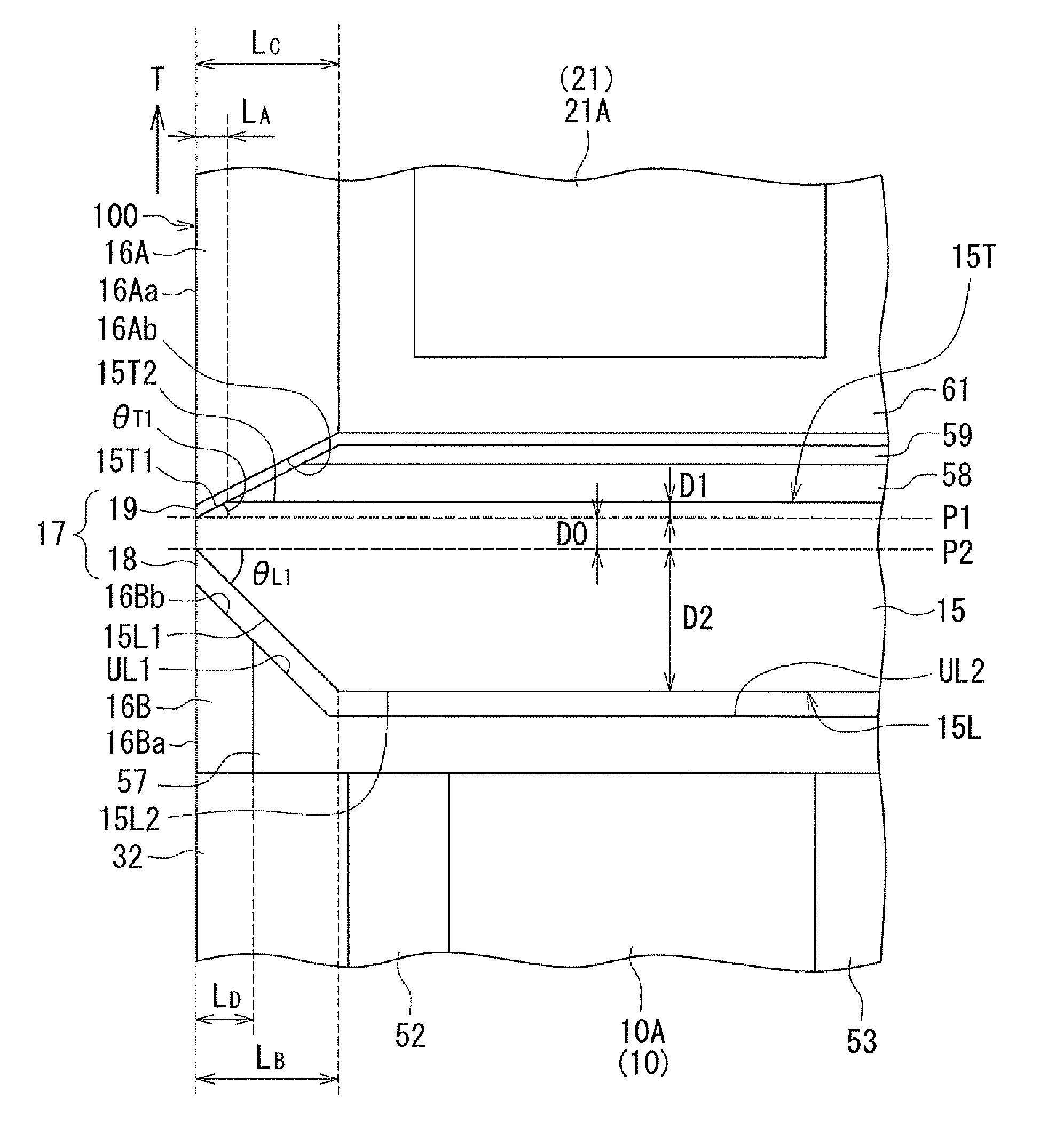
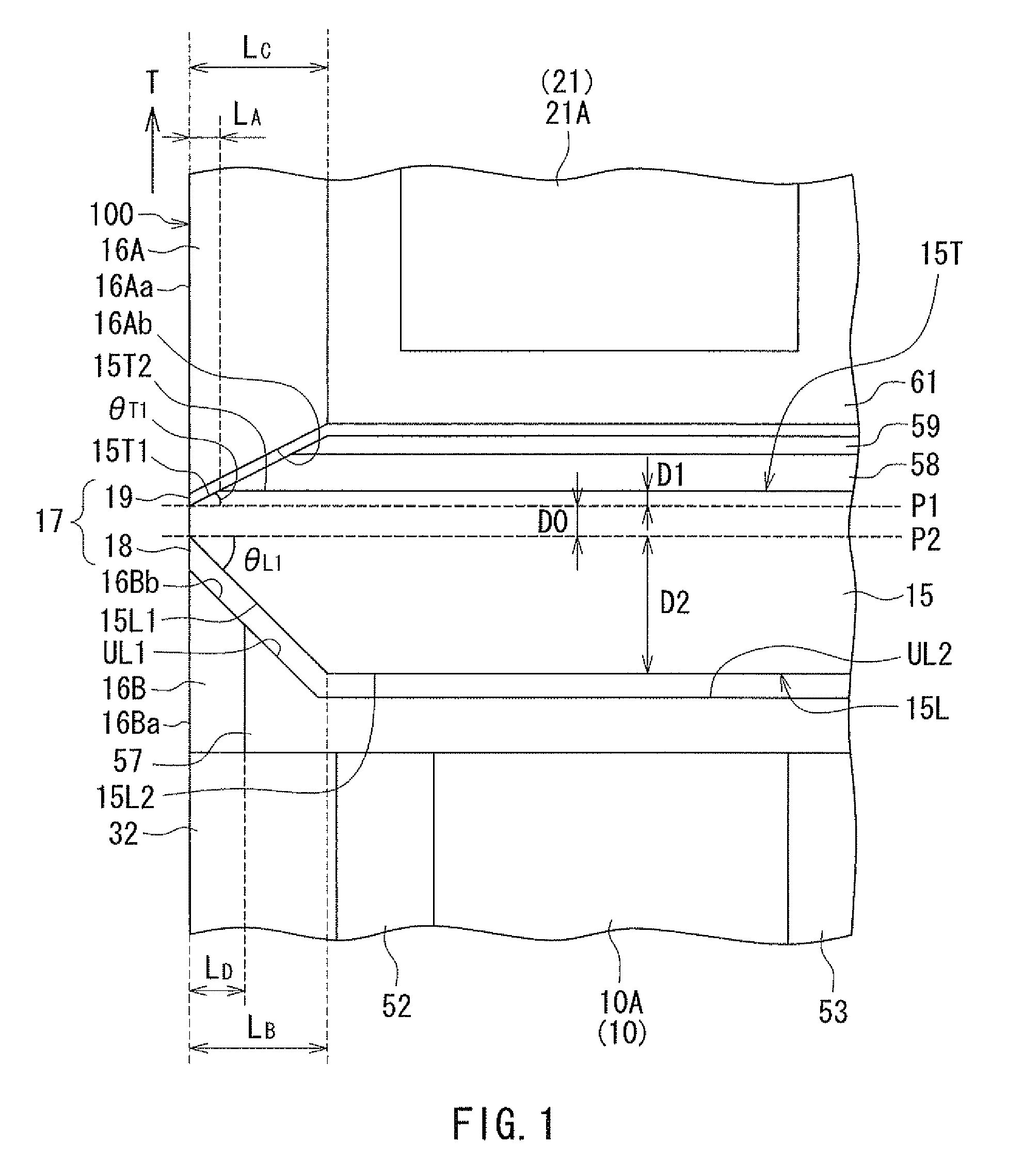
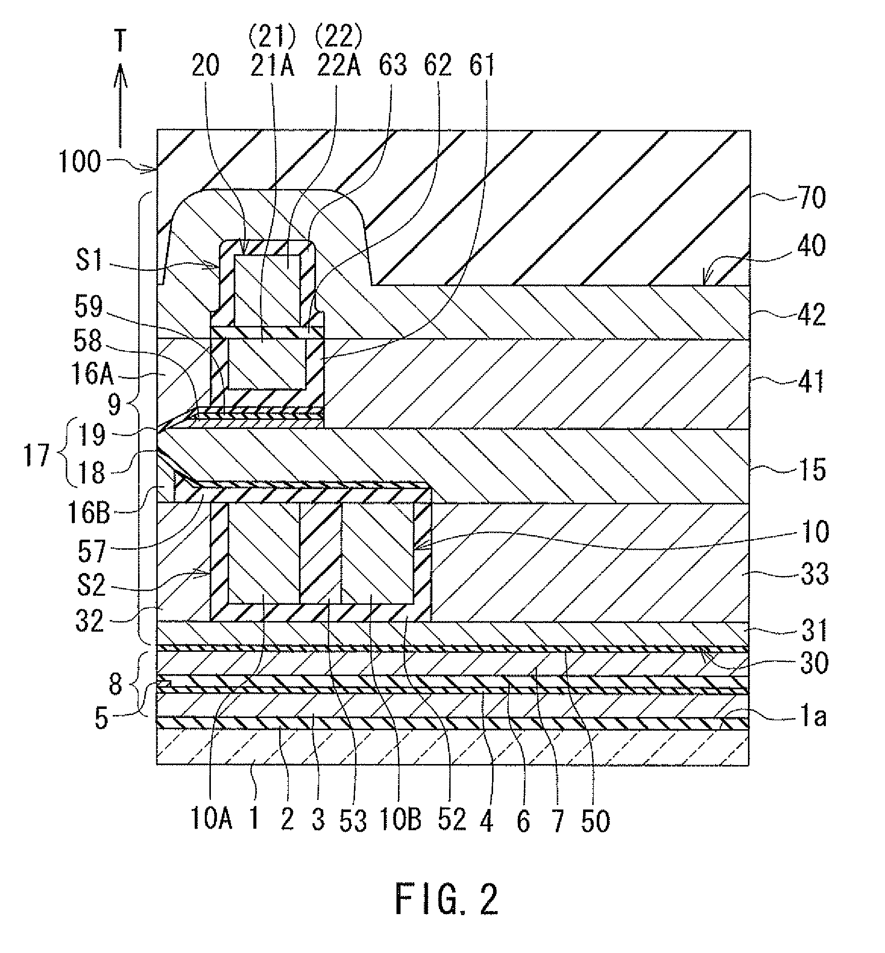
[0055]Embodiments of the present invention will now be described in detail with reference to the drawings. First, reference is made to FIG. 1 to FIG. 6 to describe the configuration of a magnetic head according to a first embodiment of the invention. FIG. 1 is a cross-sectional view showing a part of a main pole in the vicinity of a medium facing surface in the magnetic head according to the present embodiment. FIG. 2 is a cross-sectional view of the magnetic head according to the present embodiment. Note that FIG. 1 and FIG. 2 show cross sections perpendicular to the medium facing surface and the top surface of the substrate. The arrows with the symbol T in FIG. 1 and FIG. 2 indicate the direction of travel of the recording medium. FIG. 3 is a front view showing the medium facing surface of the magnetic head according to the present embodiment. FIG. 4 is a plan view showing a second portion of a coil of the magnetic head according to the present embodiment. FIG. 5 is a plan view sh...

second embodiment

[0143]A magnetic head according to a second embodiment of the invention will now be described with reference to FIG. 14 and FIG. 15. FIG. 14 is a plan view showing a plurality of second coil elements of the coil of the magnetic head according to the present embodiment. FIG. 15 is a plan view showing a plurality of first coil elements of the coil of the magnetic head according to the present embodiment.

[0144]The magnetic head according to the present embodiment is different from the magnetic head according to the first embodiment in the following respects. In the magnetic head according to the present embodiment, the coil is wound approximately two turns around the main pole 15. The coil of the present embodiment has two line-shaped portions 11 and 12 shown in FIG. 14, instead of the second portion 10 of the first embodiment shown in FIG. 4. The coil of the present embodiment further has a first layer 21 and a second layer 22 shaped as shown in FIG. 15, instead of the first layer 21 ...

third embodiment

[0148]A magnetic head according to a third embodiment of the invention will now be described with reference to FIG. 16 to FIG. 19. FIG. 16 is a cross-sectional view of the magnetic head according to the present embodiment. Note that FIG. 16 shows a cross section perpendicular to the medium facing surface and the top surface of the substrate, or the main cross section, in particular. FIG. 17 is a plan view showing a second portion of the coil of the magnetic head according to the present embodiment. FIG. 18 is a plan view showing a first layer of a first portion of the coil of the magnetic head according to the present embodiment. FIG. 19 is a plan view showing a second layer of the first portion of the coil of the magnetic head according to the present embodiment.

[0149]The magnetic head according to the present embodiment is different from the magnetic head according to the first embodiment in the following respects. The coil of the present embodiment includes a first portion 120 an...


PUM


Abstract

A main pole has a top surface including a first portion and a second portion. The main pole has a bottom end including a third portion and a fourth portion. Each of the first and third portions has a first end located in a medium facing surface. The first portion is inclined relative to the medium facing surface and a first virtual plane that passes through the first end and is perpendicular to the medium facing surface and to the direction of travel of a recording medium. The third portion is inclined relative to the medium facing surface and a second virtual plane that passes through the first end and is perpendicular to the medium facing surface and to the direction of travel of the recording medium. The first portion is smaller than the third portion in length in a direction perpendicular to the medium facing surface.

Description

BACKGROUND OF THE INVENTION[0001]1. Field of the Invention[0002]The present invention relates to a magnetic head for perpendicular magnetic recording that is used for writing data on a recording medium by means of a perpendicular magnetic recording system, and more specifically, to a magnetic head for perpendicular magnetic recording that has a main pole and a shield.[0003]2. Description of Related Art[0004]The recording systems of magnetic read / write apparatuses include a longitudinal magnetic recording system wherein signals are magnetized in a direction along the plane of the recording medium (the longitudinal direction) and a perpendicular magnetic recording system wherein signals are magnetized in a direction perpendicular to the plane of the recording medium. It is known that the perpendicular magnetic recording system is harder to be affected by thermal fluctuation of the recording medium and capable of providing higher linear recording density, compared with the longitudinal...

Claims


Application Information

Patent Timeline
IPC IPC(8): G11B5/127
CPCG11B5/1278G11B5/3116G11B5/315G11B5/3163
Inventor SASAKI, YOSHITAKAITO, HIROYUKISATO, KAZUKITANEMURA, SHIGEKIARAKI, HIRONORIIIJIMA, ATSUSHI
Owner HEADWAY TECH INC
Why Eureka
Try Eureka