
Image forming apparatus

a technology of forming apparatus and forming chamber, which is applied in the direction of electrographic process apparatus, instruments, optics, etc., can solve the problems of affecting the effect of printing, affecting the accuracy of removal state, and consuming a lot of time, so as to achieve accurate and inexpensive detection and inexpensive detection

Inactive Publication Date: 2012-09-25
CANON KK
View PDF5 Cites 0 Cited by
  • Summary
  • Abstract
  • Description
  • Claims
  • Application Information

AI Technical Summary

Benefits of technology

[0007]A principal object of the present invention is to accurately and inexpensively detect a removal state of a seal member of a cartridge in an image forming apparatus of the type wherein the removal of the seal member is automatically performed.
[0008]Another object of the present invention is to inexpensively detect whether or not a seal member of a cartridge is performed in an image forming apparatus of the type wherein the removal of the seal member is performed by a user.

Problems solved by technology

With respect to the cartridge provided with the automatic removing device, there is no failure in removal of the seal member by the user but there is possibility that the seal member is broken during automatic removal thereof.
Further, in the case where the image forming apparatus is not provided with a means for detecting the removal of the seal member, an automatic removing operation is required also when the cartridge which has already been subjected to the removal of the seal member is inserted into the apparatus, so that it takes much time until the user can effect printing.

Method used


Image

  • Image forming apparatus
  • Image forming apparatus
  • Image forming apparatus

Examples


embodiment 1

[Embodiment 1]

(1) Image Forming Portion

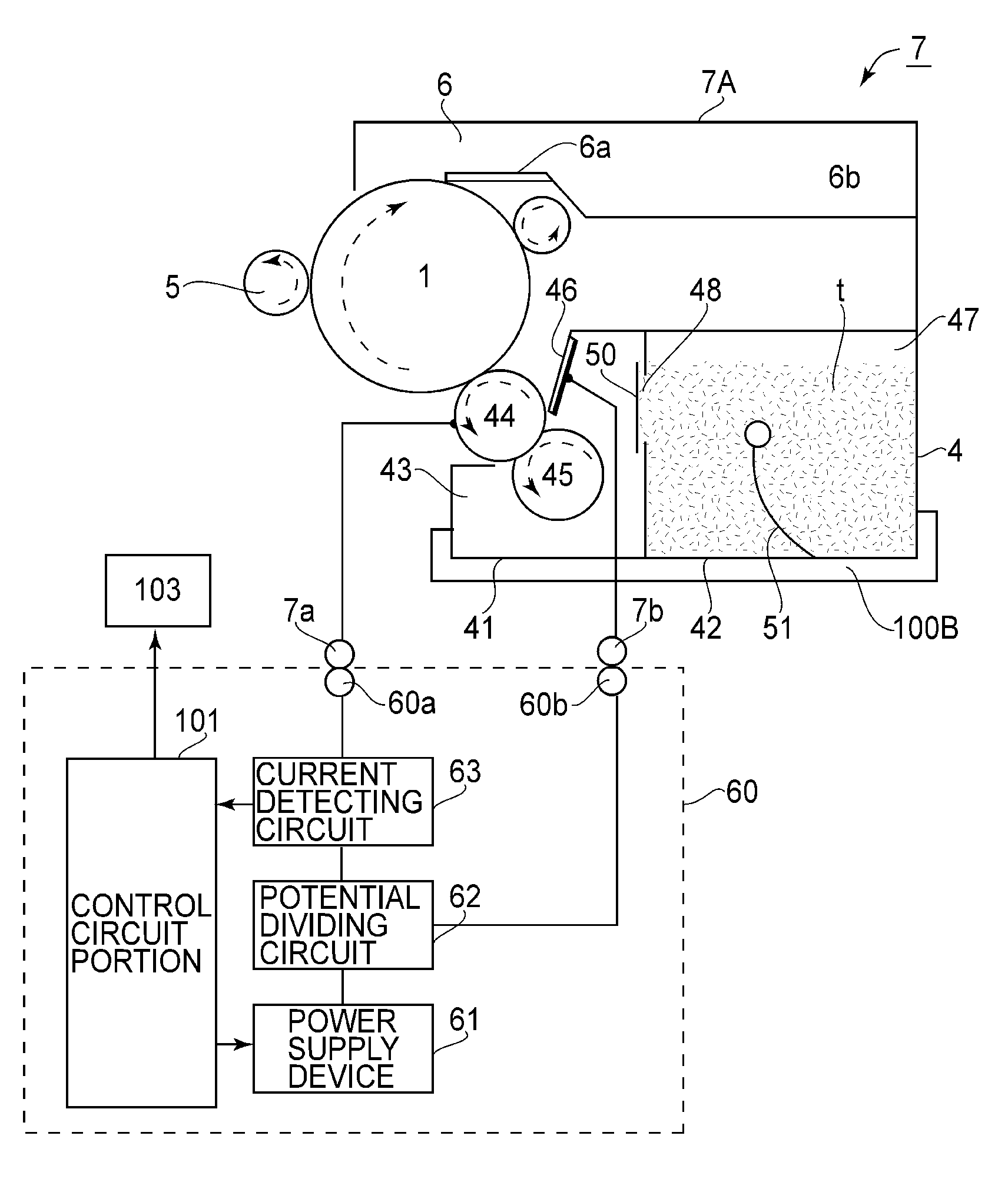
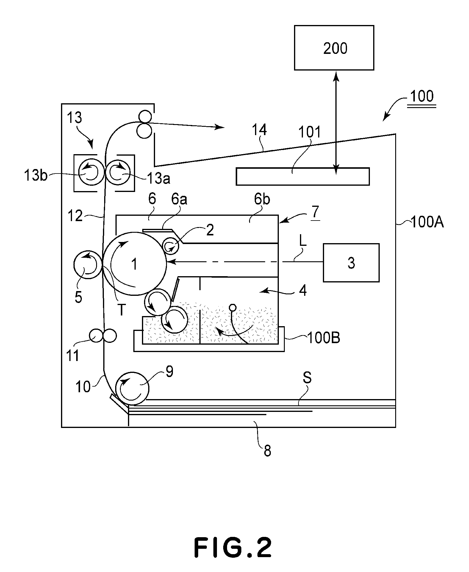
[0019]FIG. 2 is a schematic structural view of an image forming apparatus 100 in this embodiment. The image forming apparatus 100 is an electrophotographic image forming process for forming an image on a recording material (medium) S by applying a series of electrophotographic image forming processes including charging, exposure, development, transfer, and cleaning to a rotatable electrophotographic photosensitive member 1 as an image bearing member. Further, the printer is of a cartridge type in which a process cartridge 7 provided with an automatic removing device (hereinafter referred to as a cartridge) is detachably mounted to a cartridge mounting portion 100B in a main assembly 100A of the image forming apparatus 100 (herein referred to as an apparatus main assembly).

[0020]Specifically, an image is formed on the recording material correspondingly to an electric image signal input from an external host device 200 such as a personal computer...

embodiment 2

[Embodiment 2]

[0055]In this embodiment, cartridge such that the potential difference provided between the developing roller 44 and the regulating blade 46 during the seal member automatic winding-up is smaller than that during normal printing (during execution of the printing operation) is executed. First, the reason why the above control is executed will be described. In order to suppress melting of the developer onto the regulating blade 46, also during the normal printing, the provision of the potential difference between the developing roller 44 and the regulating blade 46 is effective. For the purpose of suppressing the melting of the developer, the potential difference may preferably be as large as possible. However, when the potential difference is increased, leakage is caused to occur between the developing roller 44 and the regulating blade 46, so that the surface potential of the developing roller 44 approaches the dark portion potential of the photosensitive drum 1. As a ...

embodiment 3

[Embodiment 3]

[0059]In this embodiment, a cartridge provided with no automatic removing device is employed. In the case of this cartridge, the end portion 50d of the extended portion 50c of the seal member 50 is protruded from the right-side surface of the cartridge 7 as shown in FIG. 8, thus constituting a handle at the time of removing the toner seal (seal member) 50 by the user. The user holds the end portion 50d of the seal member 50 before the fresh cartridge 7 is mounted in the apparatus main assembly and pulls out the seal member 50 to the outside the cartridge 7, thus removing the seal member 50 (manual removal). As a result, the opening 48 is unsealed. The cartridge 7 is mounted to the mounting portion 100B of the apparatus 100A and is used. That is, the cartridge 7 is detachably provided to the apparatus main assembly 100A in the state in which the seal member 50 of the cartridge 7 has been subjected to the manual removal.

[0060]When the seal member 50 is removed and then t...


PUM


Abstract

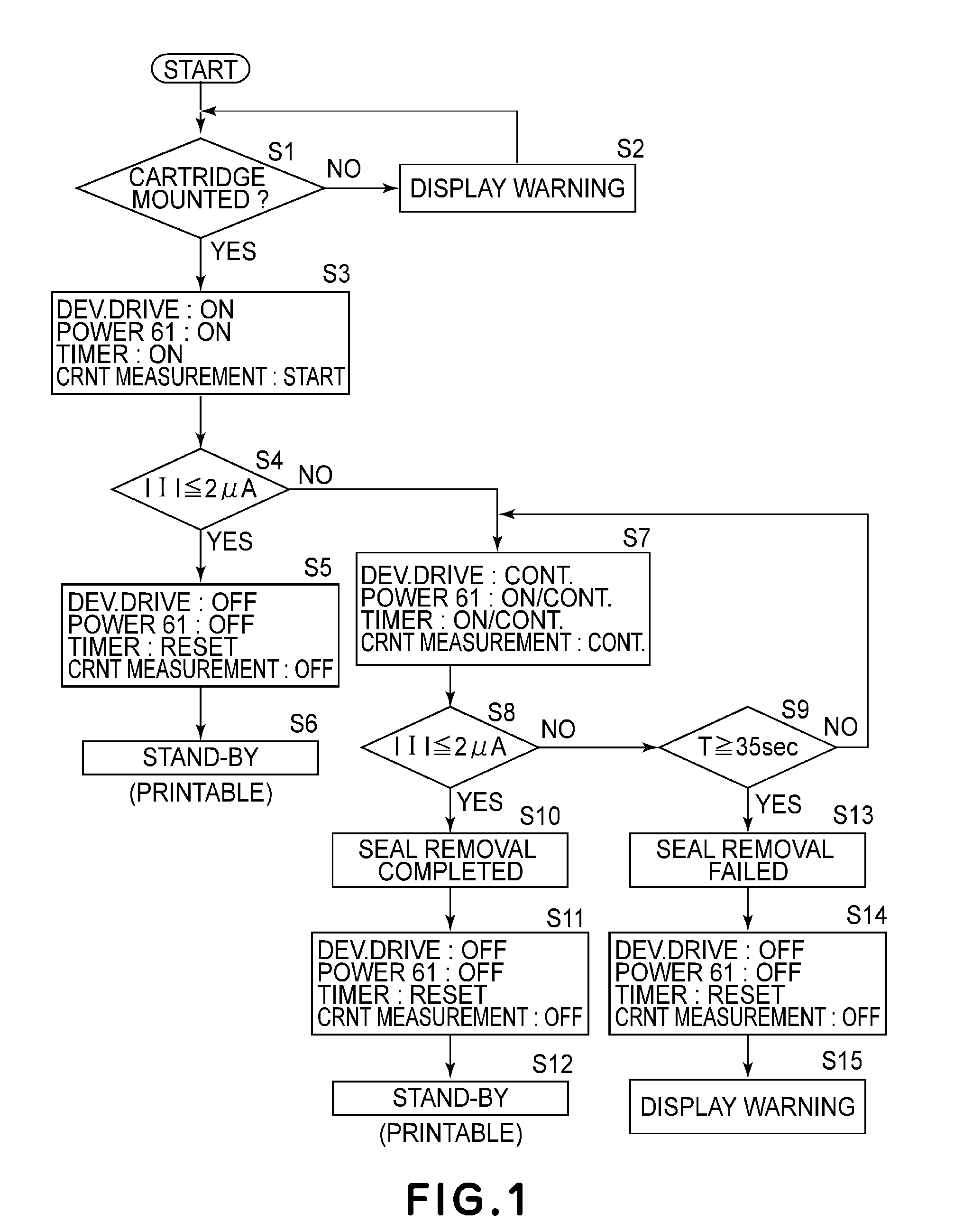
An image forming apparatus includes a cartridge detachably mountable to a main assembly thereof. The cartridge includes a developer carrying member for carrying a developer, a conductive member contactable to the carrying member, a developing chamber for holding the carrying member and the conductive member, a developer accommodating chamber for accommodating the developer, and a seal member for sealing an opening between the developing chamber and the developer accommodating chamber. The apparatus further includes a seal member removing device, and a control device. The control device controls concurrently performing seal member removal and driving of the carrying member when the cartridge is mounted to the main assembly and then sends a detection signal signaling failure of removal of the seal member when a potential difference is provided between the carrying member and said conductive member during the execution of the control.

Description

FIELD OF THE INVENTION AND RELATED ART[0001]The present invention relates to an image forming apparatus, to which a cartridge is detachably mountable, for forming an image on a recording material (medium). Here, the image forming apparatus includes those of an electrophotographic type, an electrostatic recording type, a magnetic recording type, and the like, such as a copying machine, a printer (e.g., an LED printer, a laser beam printer, or the like), a facsimile machine, and the like. An image bearing member is a member on which a latent image (electrostatic latent image, potential latent image, resistive latent image, magnetic latent image, or the like) to be developed with a developer is to be formed. For example, as the image bearing member, it is possible to use an electrophotographic photosensitive member (photoconductor) in an electrophotographic process, an electrostatic recording dielectric member in an electrostatic recording process, a magnetic recording member in a magn...

Claims


Application Information

Patent Timeline
Patent Type & Authority Patents(United States)
IPC IPC(8): G03G15/08
CPCG03G15/0882
Inventor KIHARA, HIDEOITO, MOTONARI
Owner CANON KK
Learn More