Starting power generation apparatus and starting power generation method
a power generation apparatus and power generation method technology, applied in the direction of engine starters, electric generator control, machines/engines, etc., can solve the problems of increasing the price of acg starter motors and the price of three-phase dc brushless motors, and achieve the effect of simple method and inexpensive detection of rotor positions
- Summary
- Abstract
- Description
- Claims
- Application Information
AI Technical Summary
Benefits of technology
Problems solved by technology
Method used
Image
Examples
second embodiment
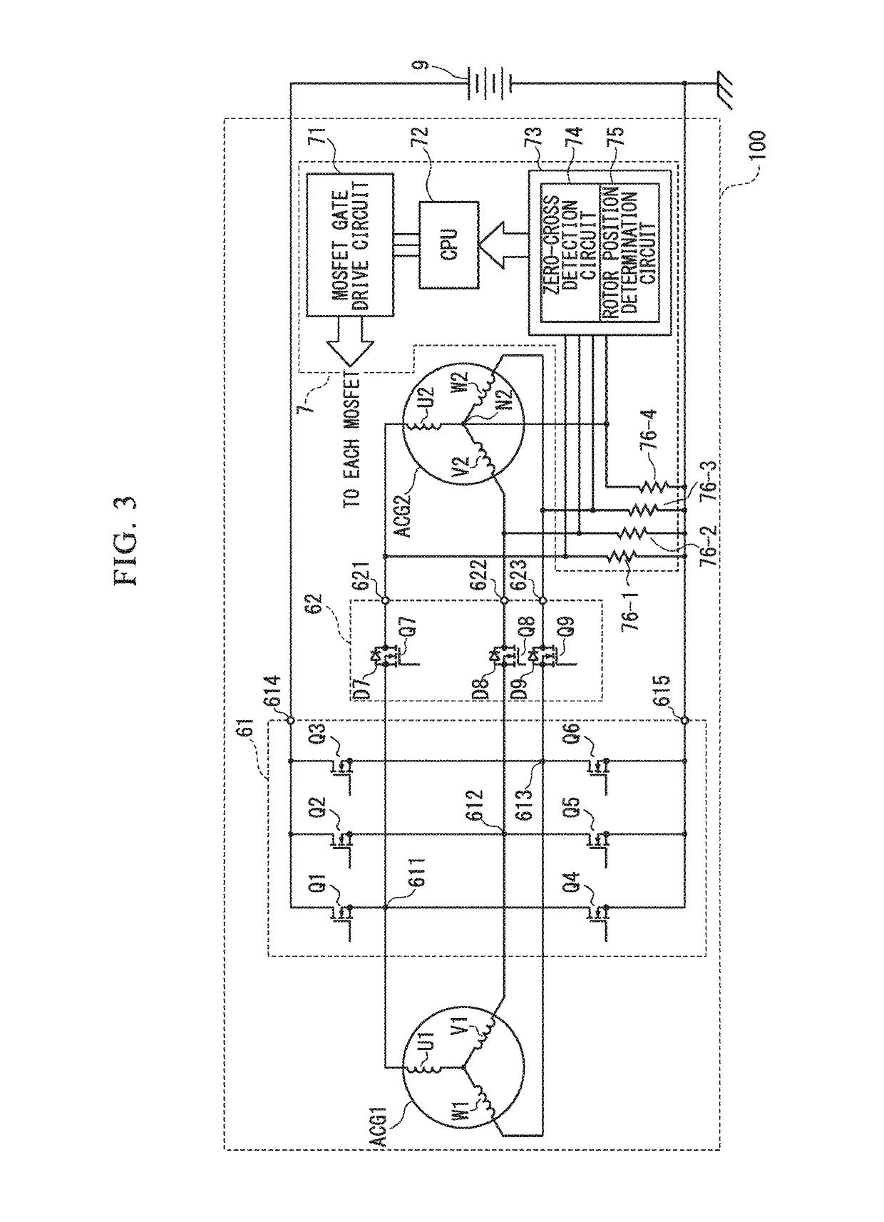
[0103]A starting power generation control apparatus 100a of the second embodiment differs from the starting power generation control apparatus 100 shown in FIG. 3 in the following points. In other words, a second power conversion unit 62a is newly provided with MOSFETs (Q10) to (Q12). In this case, a drain of the MOSFET (Q10) is connected to the drain of the MOSFET (Q7). A drain of the MOSFET (Q11) is connected to the drain of the MOSFET (Q8). A drain of the MOSFET (Q12) is connected to the drain of the MOSFET (Q9). Respective sources of the MOSFET (Q10), the MOSFET (Q11), and the MOSFET (Q12) are grounded.
[0104]Additionally, in the control unit 7a, a MOSFET gate drive circuit 71a is added with circuits for the newly provided MOSFETs (Q10) to (Q12), compared to the MOSFET gate drive circuit 71 shown in FIG. 3. Further, the CPU 72a is configured such that a program for the newly provided MOSFETs (Q10) to (Q12) is added to the CPU 72 shown in FIG. 3.
[0105]According to the starting pow...
third embodiment
[0107]The starting power generation control apparatus 100b of the third embodiment differs from the starting power generation control apparatus 100 shown in FIG. 3 in the following points. In other words, the first power conversion unit 61b is newly provided with a MOSFET (Q13) (first switching element), compared to the first power conversion unit 61 shown in FIG. 3. The MOSFET (Q13) is interposed between a positive-side DC terminal 614 and a positive-side DC terminal 616 connected to the battery 9. A drain of the MOSFET (Q13) is connected to the positive-side DC terminal 614, while a source of the MOSFET (Q13) is connected to the positive-side DC terminal 616.
[0108]A second power conversion unit 62b includes six MOSFETs (Q17) to (Q19) and (Q10) to (Q12) which constitute a three-phase bridge orthogonal converter circuit. Additionally, the orthogonal conversion unit 62b includes: a positive side DC terminal 624 on a positive side of DC input and output lines of the three-phase bridge...
fourth embodiment
[0116]In the starting power generation control apparatus 100c of the fourth embodiment, the control unit 7c includes the MOSFET gate drive circuit 71, a CPU 72c, a detection and determination circuit portion 73c, and resistors 76-1 to 76-4, and newly includes resistors 77-1 to 77-4. One end of the resistor 77-1 is connected to the winding U1, while the other end thereof is grounded. One end of the resistor 77-2 is connected to the winding V1, while the other end thereof is grounded. One end of the resistor 77-3 is connected to the winding W1, while the other end thereof is grounded. Additionally, one end of the resistor 77-4 is connected to the neutral point N1, while the other end thereof is grounded. The terminal voltages of the resistors 77-1 to 77-4 are input to the detection and determination circuit portion 73c. The detection and determination circuit unit 73c includes the zero-cross detection circuit 74 and a rotor position determination circuit 75c.
[0117]Operation of the st...
PUM
 Abstract
Description
Claims
Application Information
 - R&D
- Intellectual Property
- Life Sciences
- Materials
- Tech Scout
- Unparalleled Data Quality
- Higher Quality Content
- 60% Fewer Hallucinations
Browse by: Latest US Patents, China's latest patents, Technical Efficacy Thesaurus, Application Domain, Technology Topic, Popular Technical Reports.
© 2025 PatSnap. All rights reserved.Legal|Privacy policy|Modern Slavery Act Transparency Statement|Sitemap|About US| Contact US: help@patsnap.com


