Non-destructive ultrasound inspection with coupling check

a coupling check and ultrasound technology, applied in the direction of instruments, magnetic property measurements, analysing solids using sonic/ultrasonic/infrasonic waves, etc., can solve the problems of increasing the size of the respective test probe, the inability of the additional transducer to generate a back-face echo, and the inability to reliably detect the position of the test tube. achieve the effect of high accuracy

Inactive Publication Date: 2011-06-02
GE SENSING & INSPECTION TECH GMBH
View PDF4 Cites 3 Cited by
  • Summary
  • Abstract
  • Description
  • Claims
  • Application Information

AI Technical Summary

Benefits of technology

In view of the above-described drawbacks it is therefore an object of the invention to provide a method and an associated device for the non-destructive ultrasound inspection of a test piece which is able to detect a discontinuity less expensively and / or with a higher accuracy.

Problems solved by technology

These additional transducers generally are not designed for generating a back-face echo.
This test probe structure is disadvantageous in that a conclusion has to be drawn as to the quality of the coupling of the other transducers based on only a single coupling measurement of a transducer.
This leads to an increased unreliability of the measurement.
This leads to the respective test probe becoming relatively large and to the geometry of the test probe having to be adapted for every surface shape of a test piece, due to the multitude of ultrasonic transducers.
This complicates carrying out the ultrasound inspection and makes it more expensive.

Method used


Image

  • Non-destructive ultrasound inspection with coupling check
  • Non-destructive ultrasound inspection with coupling check
  • Non-destructive ultrasound inspection with coupling check

Examples


Embodiment Construction

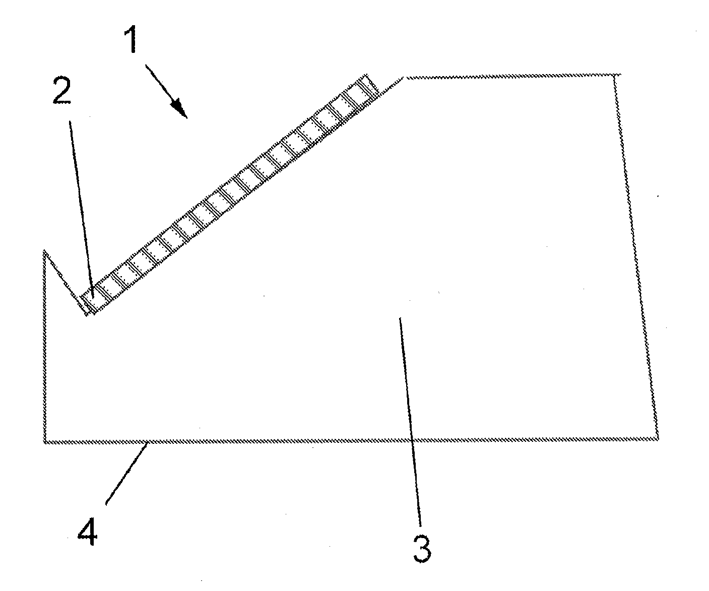
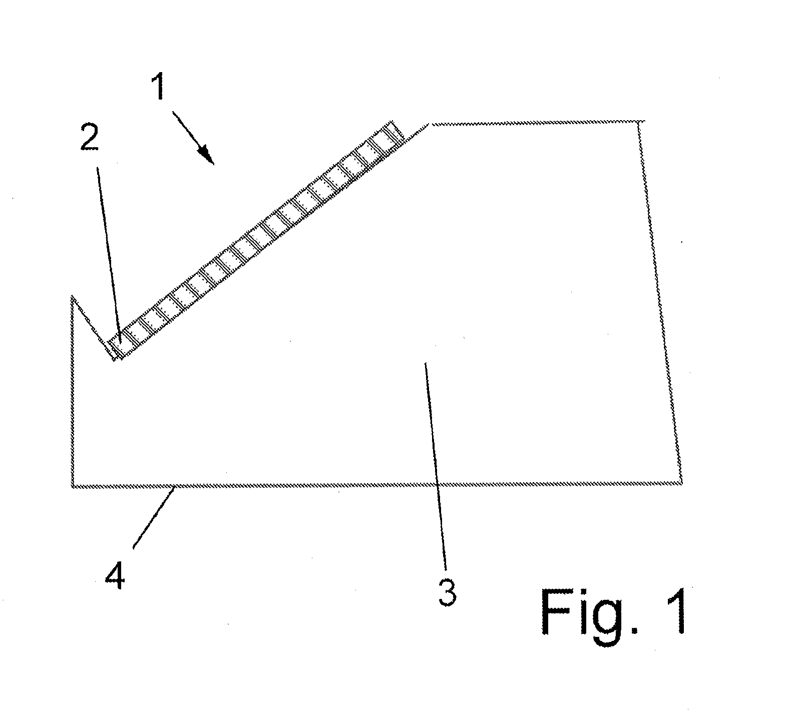
FIG. 1 schematically shows in a side view a typical structure of a phased array 1 used according to the invention with a plurality of individual ultrasonic transducers that can be controlled in a phase-accurate manner. The ultrasonic transducers 2 are disposed on a leading body 2 for coupling to the test piece 7 to be inspected. Depending on the desired transmission direction of the ultrasonic transducers 2, and depending on the shape of the surface of the test piece adjoining during the inspection, the leading body 3 can be designed to differ in the area of the contact surface 4 from the shape shown. The primary transmission direction can be changed to a certain extent by the selection of the phase shift between the ultrasonic pulses transmitted by the individual ultrasonic transducers 2. Thus, the phased array 1 can be used for carrying out the first and second test cycles.

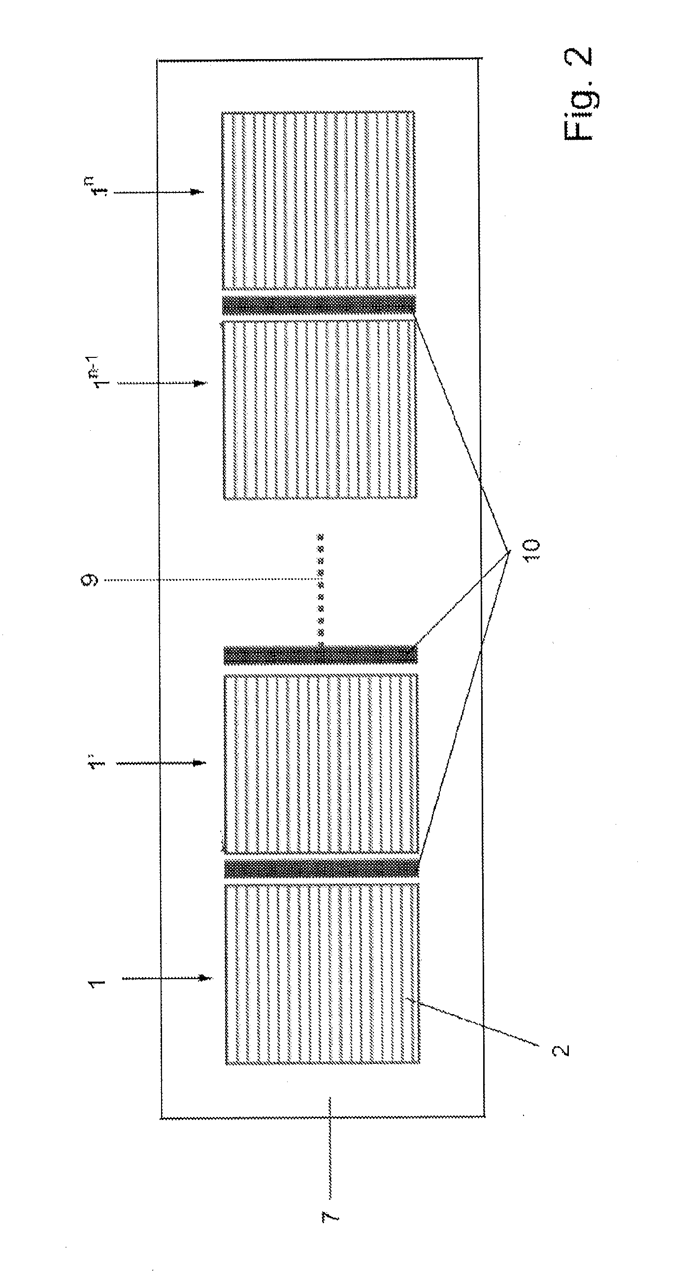
FIG. 2 shows in a schematic top view, by way of example, an arrangement according to the invention of several...


PUM

PropertyMeasurementUnit
frequencyaaaaaaaaaa
phase-accurateaaaaaaaaaa
displacementaaaaaaaaaa

Abstract

A method for non-destructive ultrasonic testing of a test piece includes a plurality of testing cycles, each of said cycles comprising a transmitting of at least one ultrasonic impulse into the test piece by a plurality of ultrasonic transducers and a receiving of the at least one ultrasonic impulse passing through the test piece by the ultrasonic transducer or optionally by other ultrasonic transducers. The plurality of ultrasonic transducers are phase-controllable and form at least one phase array. The method comprises at least one first testing cycle in which the phase-controllable ultrasonic transducers of the at least one phase array are controlled during transmitting such that the rear wall echo of the test piece is detected by said phase array during receipt. The method comprises at least one second testing cycle in which the phase-controllable ultrasonic transducer of the same phase array are controlled during transmitting.

Description

FIELD OF THE INVENTIONThe invention relates to a method and an associated device for the non-destructive ultrasound inspection of a test piece, preferably a rod or a pipe, wherein the method comprises several test cycles, each of which includes a transmission of an ultrasonic pulse into the test piece by means of several ultrasonic transducers and a reception of the ultrasonic pulse passing the test piece by the transmitting, or optionally further, ultrasonic transducers.BACKGROUND OF THE INVENTIONUltrasound testing is a suitable testing method for finding internal and external flaws in sound-conducting materials (to which most metals belong), for example in welding seams, steel forgings, casting, semi-finished products or pipes. Like all testing methods, ultrasound inspection is also standardized and is carried out in accordance with guidelines, such as according to DIN EN 10228-3 1998-07 “Zerstörungsfreie Prüfung von Schmiedestücken aus Stahl—Teil 3: Ultraschallprüfung von Schmied...

Claims


Application Information

Patent Timeline
Patent Type & Authority Applications(United States)
IPC IPC(8): G01N29/28
CPCG01N29/262
Inventor OBERDORFER, YORKFALTER, STEPHANSEMMIER, ULRICHSCHROEDER, OLAF
Owner GE SENSING & INSPECTION TECH GMBH
Why Eureka
Try Eureka