Piezoelectric element drive circuit and state detection method, and image recording device

a drive circuit and piezoelectric element technology, applied in the field of piezoelectric element drive circuit and state detection method, image recording device, can solve the problems of excessive current flow through, short circuit of an electrode due to ink leakage, drive circuit does not operate normally, etc., to detect the load state of the piezoelectric element inexpensively and suppressed circuit scale

Active Publication Date: 2016-07-07
FUJIFILM CORP
View PDF4 Cites 2 Cited by
  • Summary
  • Abstract
  • Description
  • Claims
  • Application Information

AI Technical Summary

Benefits of technology

[0022]According to this aspect, since the load resistance of the piezoelectric element is detected in a state in which the potential supplied to the input amplification unit is set to the third negative potential, the supply of the second negative potential from the second power supply unit to the output boost unit is blocked, and the individual electrode of the piezoelectric element is connected to the fourth negative potential via the first resistive element, it is possible to detect a state of the piezoelectric element inexpensively and with a suppressed circuit scale.
[0023]According to the present invention, it is possible to detect a load state of the piezoelectric element inexpensively and with a suppressed circuit scale.

Problems solved by technology

Meanwhile, in an inkjet printer, since a wiring of the droplet ejection element and an ink flow path are closely arranged, short-circuiting of an electrode due to ink leakage may occur.
When high voltage drive is performed in a state in which the electrode is short-circuited, an excessive current flows through a power supply line.
Accordingly, damage to a power field effect transistor (FET) in an output stage of the drive circuit or fuse blowout of a protection element occurs, and the drive circuit does not operate normally.
Accordingly, in a case where the circuit is adopted in a circuit of a high-speed, large-capacity load, there is a disadvantage in that performance of a push-pull circuit is not sufficiently exhibited and high-speed, large-amplitude drive is limited.
Further, there is a problem in that the power supply line becomes unstable due to a flow of a high current.

Method used


Image

  • Piezoelectric element drive circuit and state detection method, and image recording device
  • Piezoelectric element drive circuit and state detection method, and image recording device
  • Piezoelectric element drive circuit and state detection method, and image recording device

Examples


Embodiment Construction

[0034]Preferred embodiments of the present invention will be described in detail according to the accompanying drawings.

[0035][Structure of Ink-Jet Head]

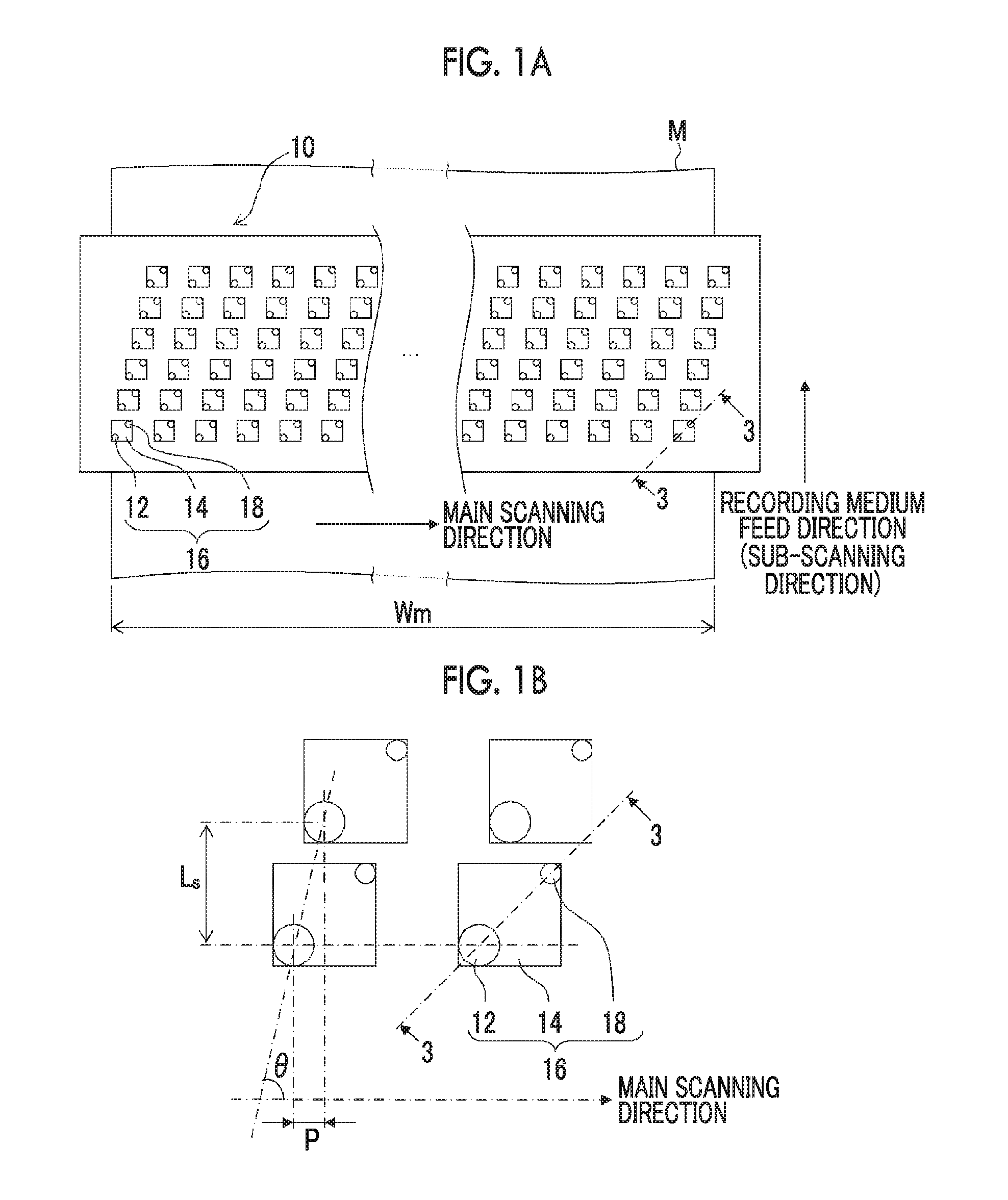
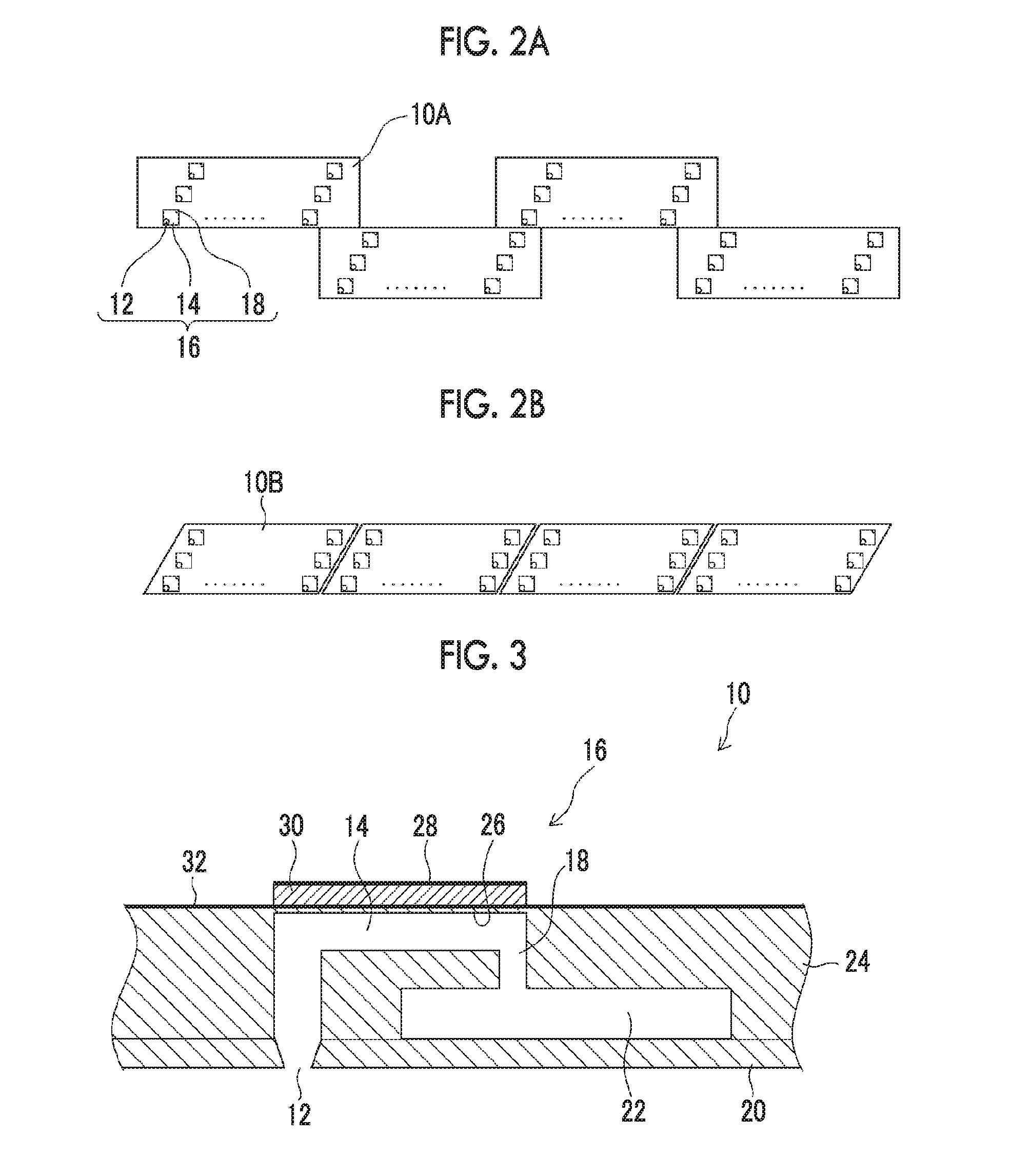
[0036]A structure of an ink-jet head according to this embodiment will first be described. FIG. 1A is a perspective plan view illustrating a structure example of the ink-jet head 10, and FIG. 1B is a partial enlarged view thereof. Further, FIGS. 2A and 2B are perspective plan views illustrating another structure example of the ink-jet head 10, and FIG. 3 is a sectional view illustrating a three-dimensional configuration of a droplet ejection element (ink chamber unit corresponding to one nozzle 12) for one channel which is a recording element unit (sectional view taken along a line 3-3 in FIGS. 1A and 1B).

[0037]As illustrated in FIG. 1A, the ink-jet head 10 has a structure in which a plurality of ink chamber units (droplet ejection elements) 16 each including, for example, a nozzle 12 which is an ink ejection port, and a pressure ch...


PUM


Abstract

Provided are a piezoelectric element drive circuit and state detection method, and an image recording device which realize state detection of a piezoelectric element inexpensively and with a suppressed circuit scale in a drive circuit for rapidly driving a large-capacity load that uses negative voltage drive. An output potential (VOUT) of a boost unit (BST) is detected in a state in which VS_AMP supplied to an amplification unit (AMP) is set to a voltage lower than a maximum rating of a transistor (FET1) by SW1, supply of VS_FET to the boost unit (BST) is blocked by SW2, and an individual electrode (28) of a piezoactuator (30) is pulled down to VS_FET via a resistor (R6).

Description

CROSS-REFERENCE TO RELATED APPLICATIONS[0001]The present application is a Continuation of PCT International Application No. PCT / JP2014 / 074079 filed on Sep. 11, 2014 claiming priority under 35 U.S.C. 119(a) to Japanese Patent Application No. 2013-191950 filed on Sep. 17, 2013. Each of the above applications is hereby expressly incorporated by reference, in their entirety, into the present application.BACKGROUND OF THE INVENTION[0002]1. Field of the Invention[0003]The present invention relates to a piezoelectric element drive circuit and state detection method, and an image recording device, and particularly, to a technology for detecting a state of a piezoelectric element that uses negative voltage drive.[0004]2. Description of the Related Art[0005]An inkjet printer in which a piezoelectric element is used as a droplet ejection element that discharges droplets is known. In a piezoelectric element drive circuit, switching of high speed, high voltage, and high current is required.[0006...

Claims


Application Information

Patent Timeline
Patent Type & Authority Applications(United States)
IPC IPC(8): B41J2/045H01L41/04
CPCB41J2/04541H01L41/042B41J2/04581B41J2/04508B41J2/0451H10N30/802H10N30/2047
Inventor HIRAKAWA, ATSUKO
Owner FUJIFILM CORP
Why Eureka
Try Eureka