Manipulator system and control apparatus

a manipulator and control apparatus technology, applied in the field of manipulator systems, can solve the problems of end pulleys, inability to recognize individual information, and complex methods

Active Publication Date: 2012-10-02
KARL STORZ GMBH & CO KG
View PDF15 Cites 945 Cited by
  • Summary
  • Abstract
  • Description
  • Claims
  • Application Information

AI Technical Summary

Benefits of technology

[0025]It is one object of the present invention to provide a manipulator system and a control apparatus, which enables detachment of a working unit under a condition in which the operating portion on the working unit is shifted from its prescribed origin position to be identified and drawn to the attention of an operator.

Problems solved by technology

Because of the necessity to easily clean and disinfect the working unit periodically, the working unit does not contain any electronic components such as sensors or the like, and the positions and origin points of the end effector and the base end pulleys cannot be detected directly.
However, in actual practice, when a connector having a large number of pins is disconnected, not all of the pins can be disconnected at the same time, and an open loop occurs momentarily.
However, with such a method, fixing and releasing of the interlock mechanism with each restoration of the origin position must be carried out repeatedly a large number of times, thus making the method complex.
Because IDs are first capable of being acquired at this time, if at the time of connection the motor phases are shifted and a connection cannot be established, the individual information cannot be recognized.
However, when the power supply is turned OFF, the connector is detached, and thereafter the power supply to the control apparatus is turned ON again, the computer system inside the control apparatus is reinitiated, so that a certain amount of time is required for rebooting.
Moreover, in Japanese Laid Open Patent Publication No. 2004-105451, no disclosure is provided concerning attachment and detachment of a connector between a manipulator main body and a control apparatus.

Method used


Image

  • Manipulator system and control apparatus
  • Manipulator system and control apparatus
  • Manipulator system and control apparatus

Examples


Embodiment Construction

[0051]Descriptions of a manipulator system 500a according to a first embodiment and a manipulator system 500b according to a second embodiment, as working mechanisms according to the present invention, together with control apparatus therefor, shall be presented below with reference to the accompanying FIGS. 1 to 20.

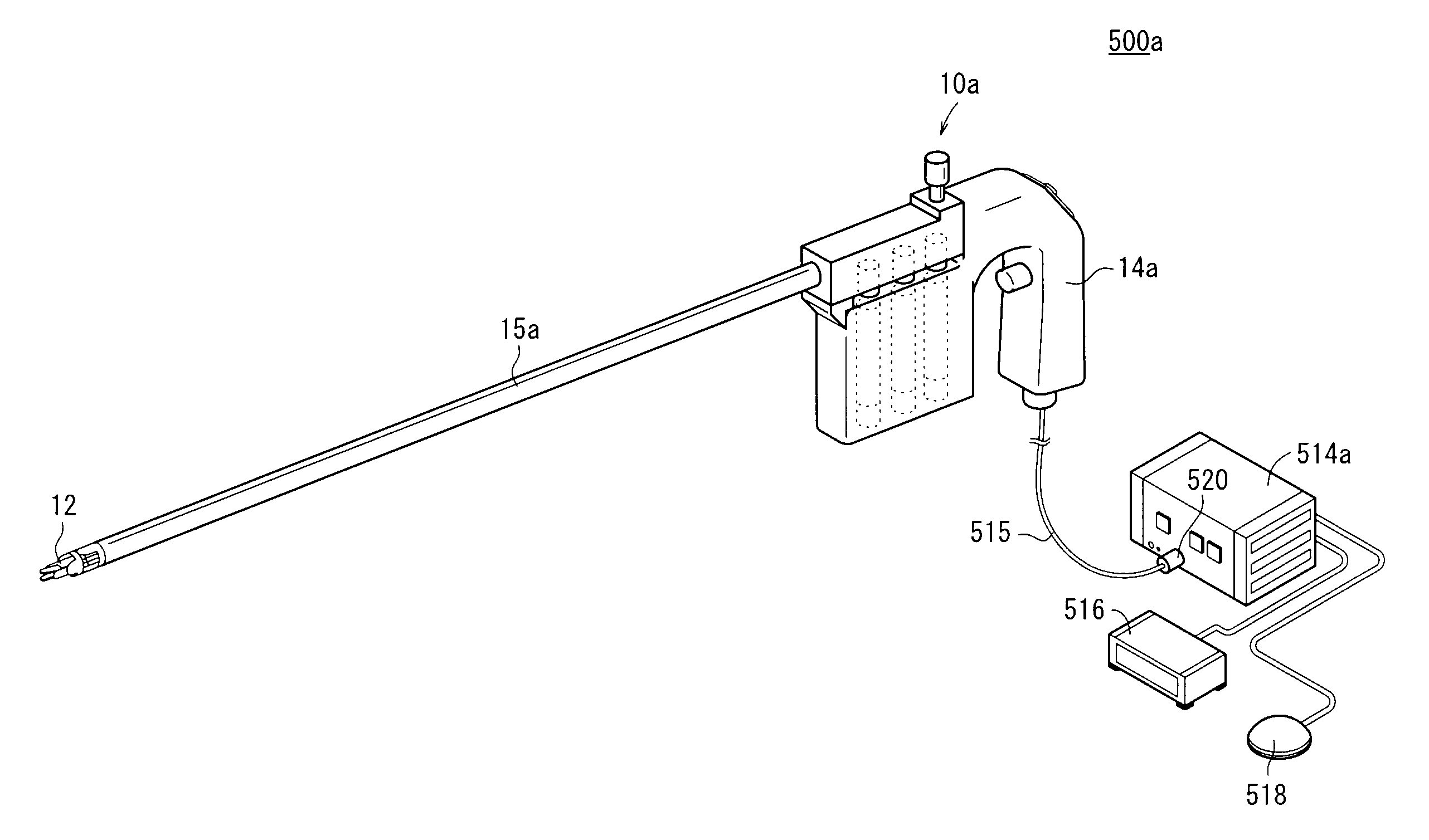
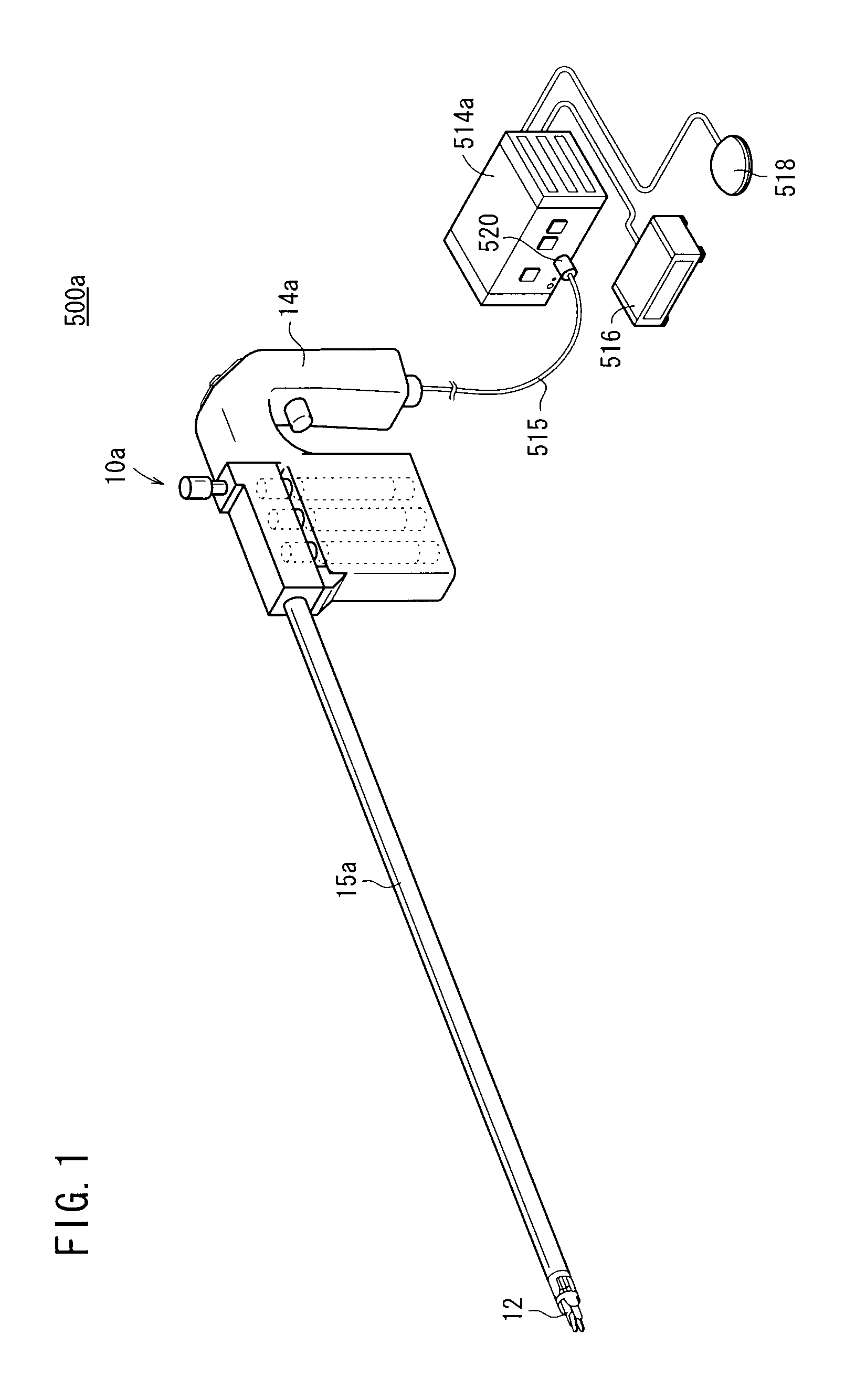
[0052]The manipulator system 500a and a control apparatus 514a therefor (see FIG. 1) according to the first embodiment, and the manipulator system 500b and a control apparatus 514b therefor (see FIG. 16) according to the second embodiment, are intended for medical use, and in particular are utilized for performing laparoscopic surgeries and the like.

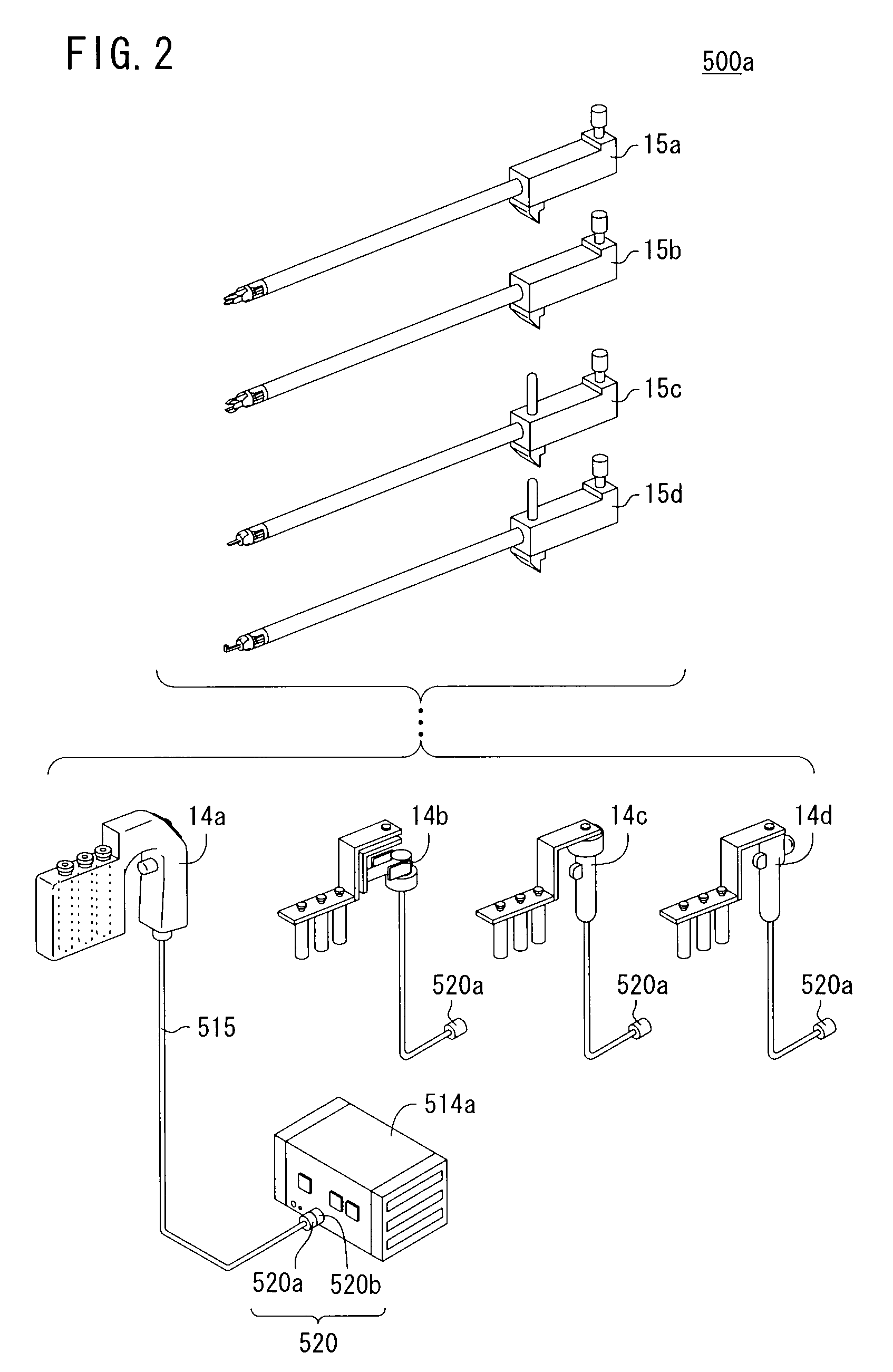
[0053]As shown in FIG. 1, the manipulator system 500a includes a manipulator (control object) 10, a control apparatus 514a, and an operating state display device 516, and a command input means 518.

[0054]The operating state display device 516, which is connected to the control apparatus 514a, displays the operating state of th...


PUM


Abstract

A manipulator has an operation command unit and an exchangeable working unit. The working unit comprises an end effector operable under actions of a control apparatus, and an ID retaining section holding an ID for individualized discrimination of the working unit. The control apparatus includes an ID identification section for identifying the ID and for determining whether the working unit is connected to the operation command unit, an origin point recognition section for recognizing whether the end effector is in a prescribed origin point position or in a non-origin point position, and a warning section which generates a detachment warning when it is determined that the end effector has been detached from the operation command unit, in the event it is determined that the end effector is in a non-origin point position.

Description

BACKGROUND OF THE INVENTION[0001]1. Field of the Invention[0002]The present invention relates to a manipulator system having a manipulator and a controller, as well as to a control apparatus for controlling a manipulator or the like. In particular, the present invention relates to a manipulator system and a control apparatus, wherein a portion or the entirety of the manipulator is structured so as to be detachable with respect to the controller.[0003]2. Description of the Related Art[0004]In laparoscopic surgery, a number of small holes are opened in a patient's abdomen or the like, and an endoscope, a manipulator (or forceps), or the like is inserted, and surgery is carried out while the surgeon observes an image from the endoscope on a monitor. In this type of laparoscopic surgery, owing to the fact that opening of the abdominal cavity is unnecessary, the burden on the patient is small, and number of days required for the post-operative recovery and number of days spent in the hos...

Claims


Application Information

Patent Timeline
Patent Type & Authority Patents(United States)
IPC IPC(8): A61B17/32
CPCA61B19/22A61B19/44A61B2017/00482A61B2019/2242A61B2019/442A61B2019/448A61B2019/4857A61B90/96A61B34/70A61B34/71A61B90/90A61B90/98A61B2090/0811
Inventor SUNAOSHI, TAKAMITSUJINNO, MAKOTOOMORI, SHIGERU
Owner KARL STORZ GMBH & CO KG
Why Eureka
Try Eureka