
Twist-tie catch twister apparatus

a twister and twisting technology, applied in the field of twisting catch twisters, can solve the problems of limited tying material, inefficient power consumption, etc., and achieve the effects of saving time and travel, avoiding tying material waste, and being easy to program

Active Publication Date: 2012-10-09
JOHNSON INT CORP
View PDF11 Cites 13 Cited by
  • Summary
  • Abstract
  • Description
  • Claims
  • Application Information

AI Technical Summary

Benefits of technology

[0014]An important object of the invention is that the program operating the motor rotating the catch twister and motor for the dual feed rollers may be easily programmed to revolve in either direction. In the case a servo motor with a multi line encoder is used the rotational speed and stopping position is achieved allowing precise repeatable operation and adjustments to be made according to the requirements of the article being tied. As an example when the hinged split ring is changed in diameter the feed roller may be simply programmed to change the length of the twist-tie material fed into the ring. The tightness of the tie onto the workpiece and the number of twists per cycle may be programmed by varying the distance the feed rollers reverse the twist-tie material as users of the apparatus often require looser or tighter ties such as 4.0 inches (10.2 cm) in a loose tie with 1½ turns or 1.0 inch (2.45 cm) in a tight tie with 4 turns. If a user is running one larger size workpiece continually, the tape reverse distance may be set for a much smaller distance, saving time and travel.
[0015]Another object of the invention is that the combination of components are not operationally sensitive to twist-tie material size or construction which permits almost all commonly used twist-tie material to be used interchangeably. Wire size and the stiffness, or softness, and the numbers of wires embedded in the material including the width and thickness are not a factor, therefore from the smallest to the largest may be used with total impunity. Employing a servo motor coupled with a multi line encoder permits this functional operation in the wide variety of materials or tie material because of its ability to set high speeds along with acceleration / deceleration values of the dual feed rollers.
[0016]Still another object of the invention is the quiet operation as, when used, electric motors ramp up smoothly creating little noise. The snap action of the split ring, twist-tie clamp and twist-tie cutter driven by electromagnetic solenoids emit only short subdued noise when energized.
[0017]A final object of the invention is the space and cost saving eliminating complicated mechanical arrangements and improving the reliability of the overall assembly.

Problems solved by technology

In the past pneumatic, hydraulic and electrical power sources have been utilized in various tying machines with some success however most are complicated, noisy, inefficient in power consumption and limited to a particular tying material.

Method used


Image

  • Twist-tie catch twister apparatus
  • Twist-tie catch twister apparatus
  • Twist-tie catch twister apparatus

Examples


Embodiment Construction

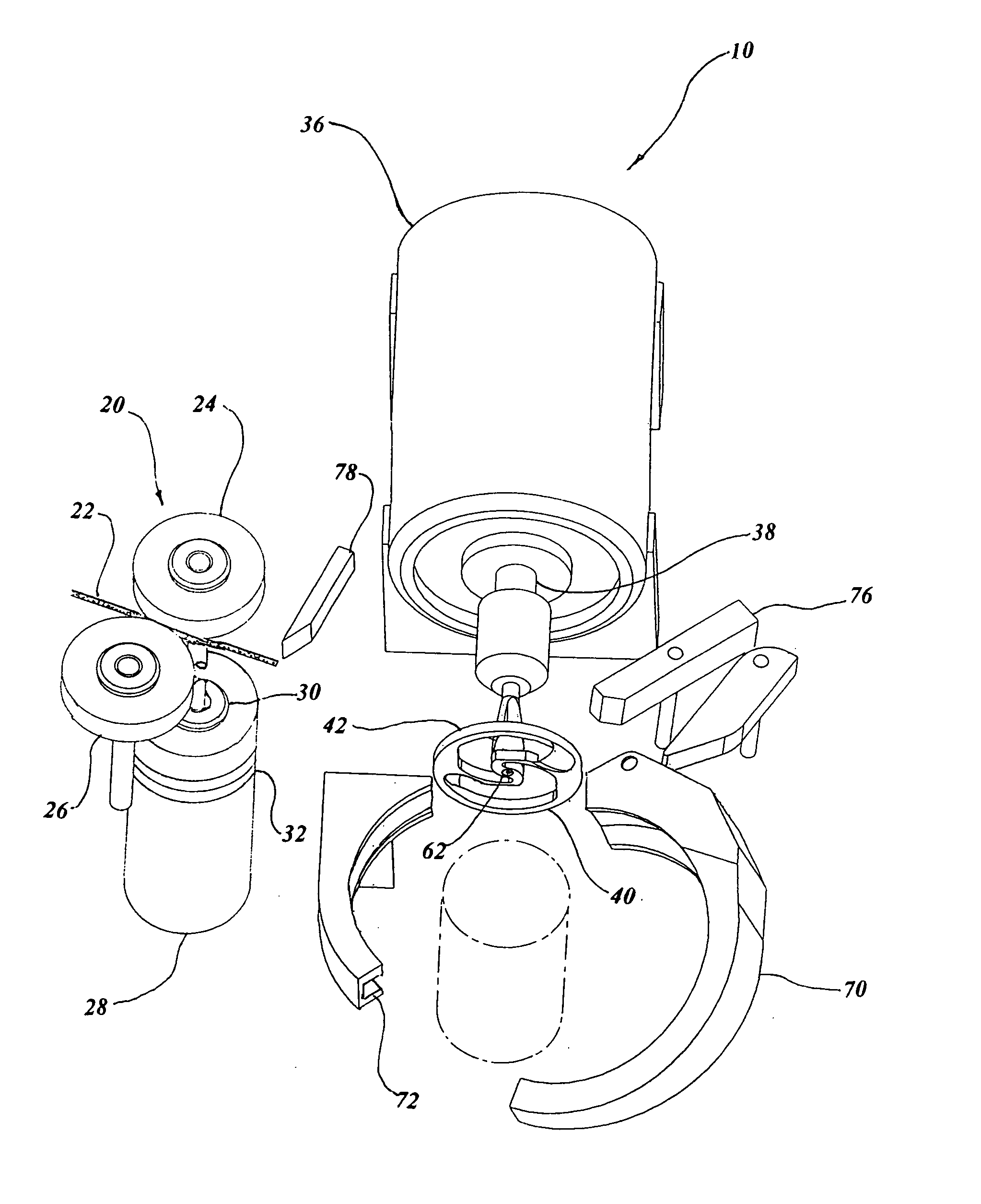
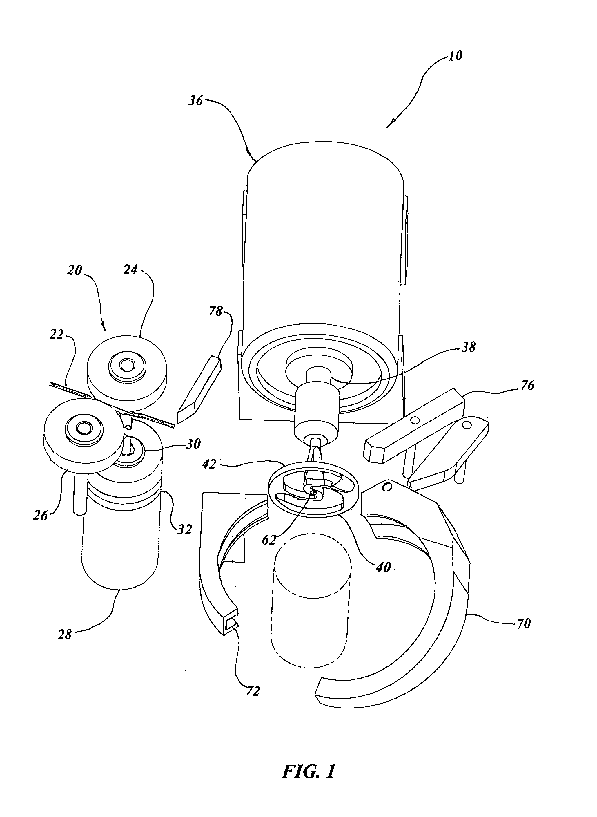
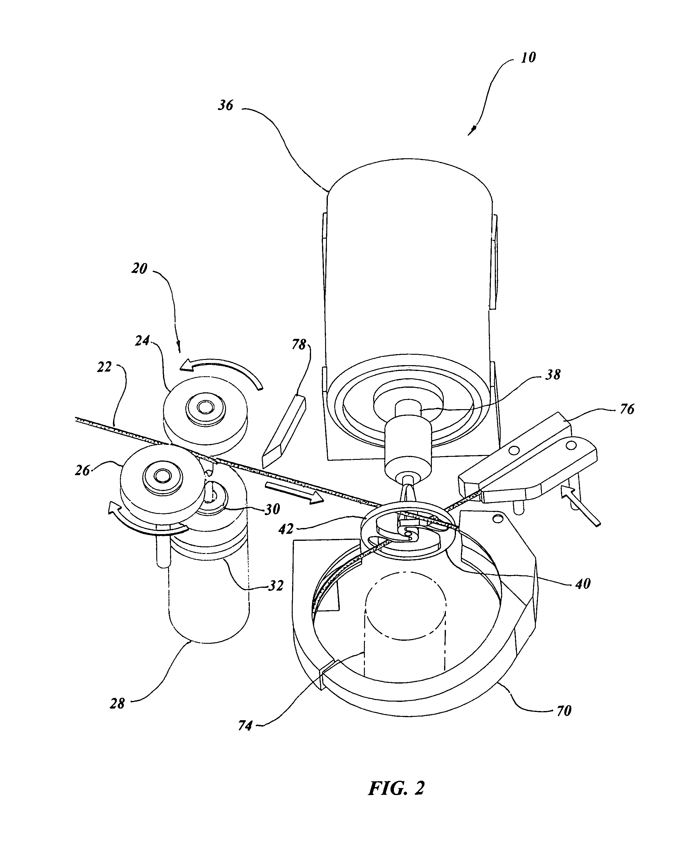
[0029]The best mode for carrying out the invention is presented in terms of a preferred embodiment. This preferred embodiment is shown in FIGS. 1 through 10 and is comprised of a twist-tie catch twister apparatus 10 for twisting together ends of the tie-wrap enclosing an article, with the article hereafter known as the workpiece.

[0030]Dual feed rollers 20 are employed for feeding and reversing twist-tie material 22 that is positioned between the rollers 20. The dual feed rollers 20 consist of a power roller 24 and a follower roller 26 intimately engaged together to transmit twist-tie material 22 in either direction. The power roller 24 is driven by a feed roller motor 28, such as a step motor or preferably by a servo motor with a multi-line encoder energized with an AC or DC current. Alternatively a pneumatic / hydraulic linear to rotary motor may be employed. In any case the motor driving the power roller 24 includes a one-way clutch 30 and a slip-clutch 32, with the power roller 24 ...


PUM

PropertyMeasurementUnit
diameteraaaaaaaaaa
diameteraaaaaaaaaa
diameteraaaaaaaaaa

Abstract

A twist-tie catch twister apparatus is taught that consists of dual feed rollers that feed twist-tie material through a back opening in a catch twister into the groove of a peripheral ring, which continues around the ring penetrating the front side of the catch twister through a second opening. The twist-tie material is then retained by a twist-tie clamp and the rollers reverse rotation drawing the twist-tie material onto a workpiece. The catch twist motor rotates the catch twister one half turn twisting to hold tension on the workpiece. A twist-tie cutter, positioned between the feed rollers and split ring, severs the twist-tie material and the twist-tie tape clamp opens with the motor rotating the catch twister a predetermined number of turns and then reverses at least one half turn to release the twisted material and the split ring opens for removal of the twist-tie secured workpiece.

Description

TECHNICAL FIELD[0001]The present invention relates to an apparatus for twisting together ends of twist-tie material to enclose an article in general. More specifically to a twist-tie catch twister that permits twist-tie material to enter the front and back of the twister and be rotated by a motor to coil the twist-tie material around the article in a controlled manner.BACKGROUND ART[0002]Previously, many types of twist tying machines and apparatus have been used in endeavoring to provide an effective means to close the open end of an outer covering over an article such as bread wrappers, produce products etc.[0003]A search of the prior art did not disclose any patents that possess the novelty of the instant invention; however the following U.S. patents are considered related:[0004]Pat. NumberInventorIssue Date3,898,924Mead et al.Aug. 12, 19754,177,842DilleyDec. 11, 19794,117,988MooreOct. 3, 19784,559,977DilleyDec. 24, 19855,389,190Larsen et al.Feb. 14, 19955,613,530Contreras et al.M...

Claims


Application Information

Patent Timeline
Patent Type & Authority Patents(United States)
IPC IPC(8): B65B13/28B21F9/02B21F15/04
CPCB21F15/04B21F3/00
Inventor HOFFA, JACK L.
Owner JOHNSON INT CORP
Learn More