Hydraulic hose coupler
- Summary
- Abstract
- Description
- Claims
- Application Information
AI Technical Summary
Benefits of technology
Problems solved by technology
Method used
Image

Examples
Embodiment Construction
A. Overview
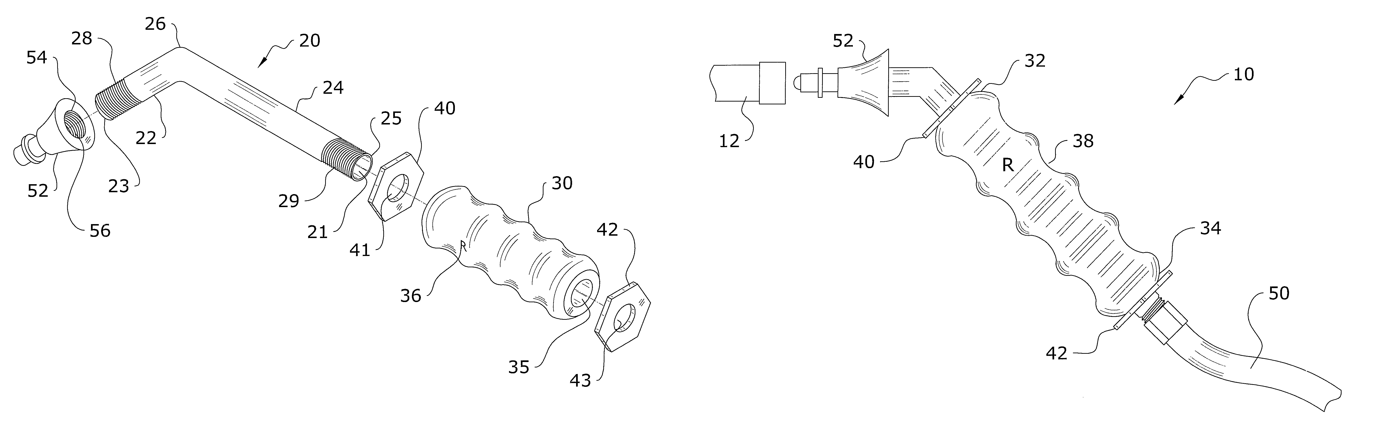
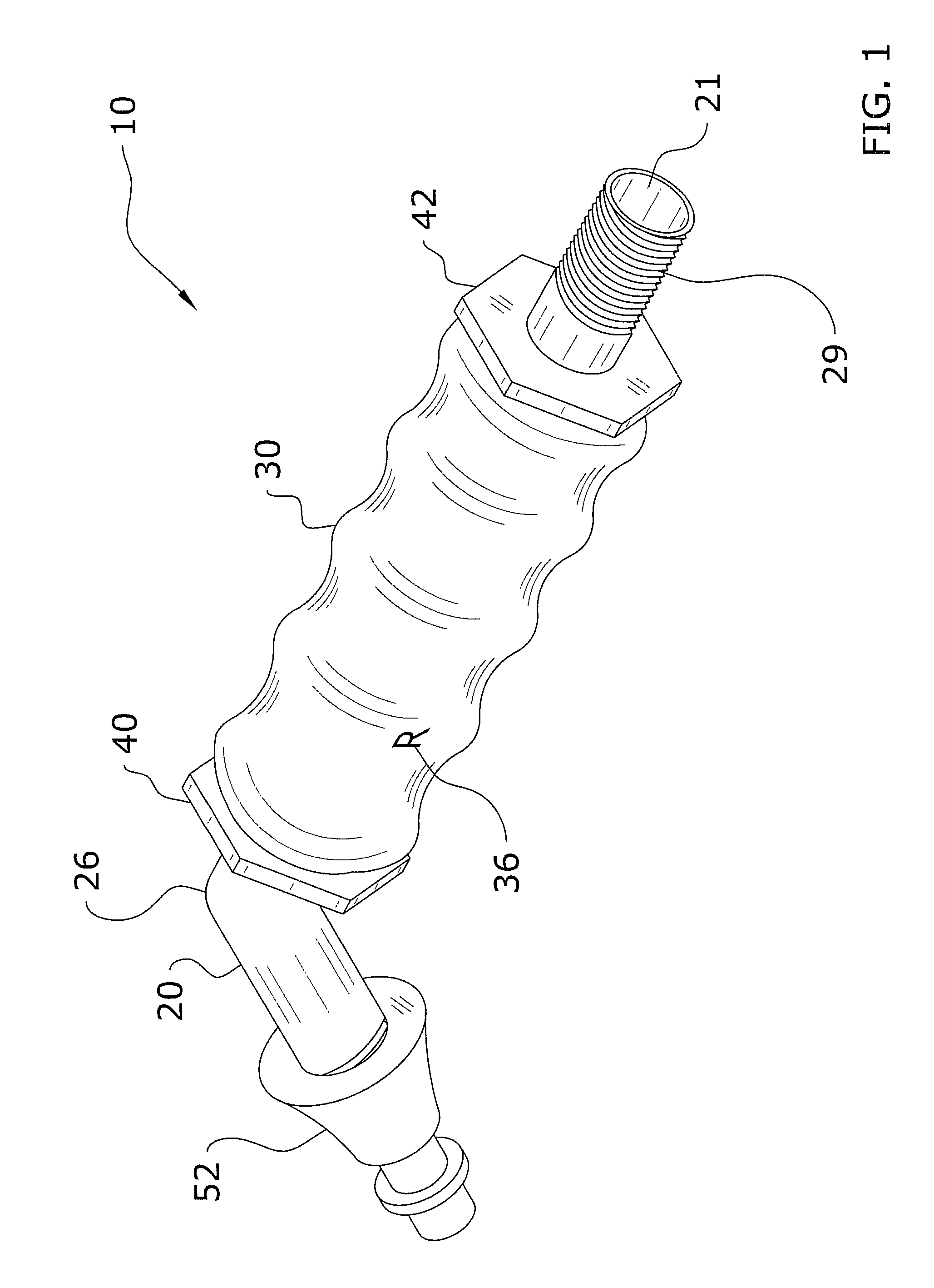
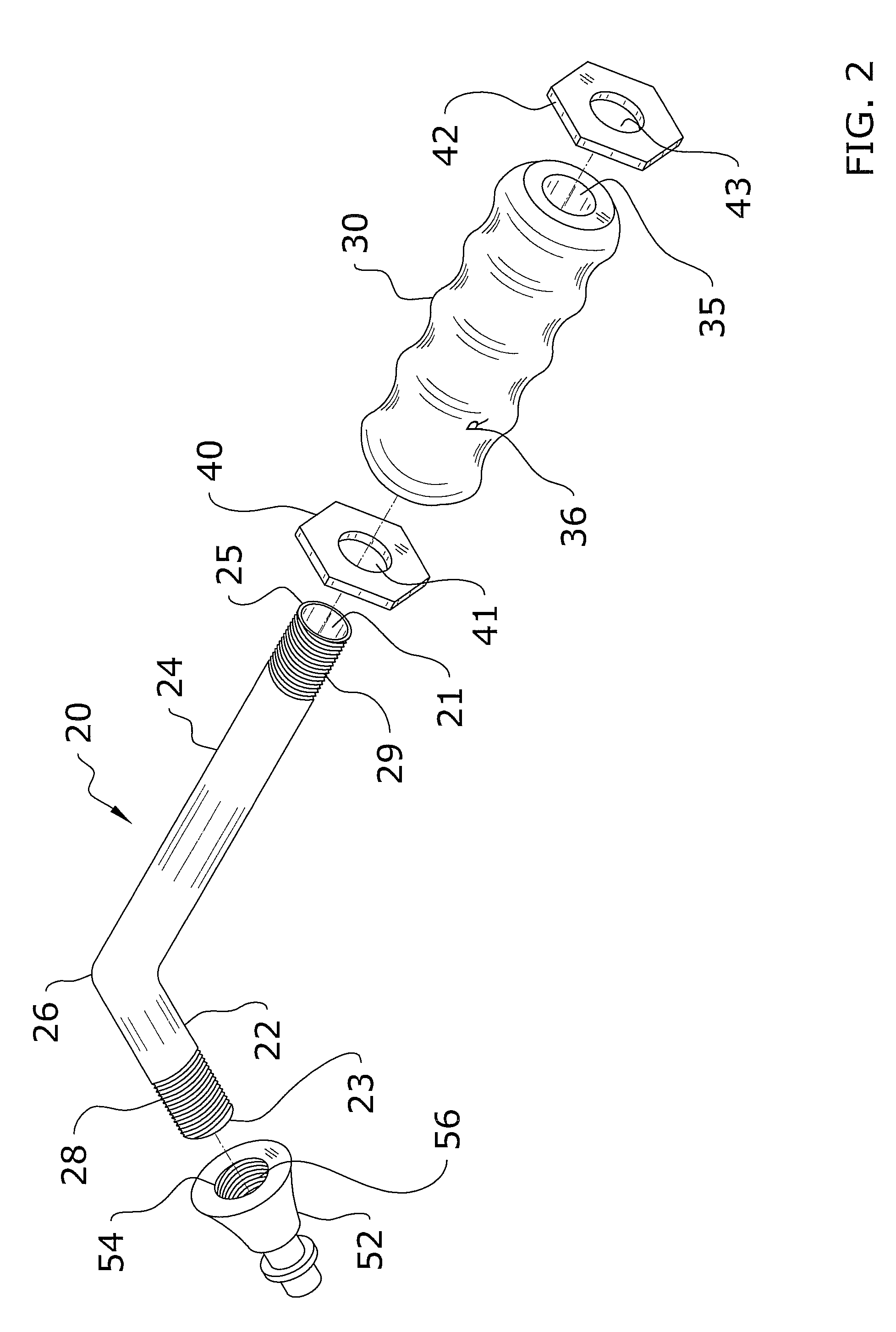
[0018]Turning now descriptively to the drawings, in which similar reference characters denote similar elements throughout the several views, FIGS. 1 through 5 illustrate a hydraulic hose coupler 10, which comprises a tube member 20 having a first portion 22, a joint 26 and a second portion 24, wherein the first portion 22 and second portion 24 extend away from the joint 26 at an approximate 135 degree angle with respect to each other. The first portion 22 of the tube member 20 will generally include a threaded first end 23 for removably connecting to a hydraulic connector 52. The second portion 24 of the tube member 20 will generally include a threaded second end 25 for removably connecting to a hydraulic hose 50. An ergonomic handle 30 will preferably extend around the second portion 24 of the tube member 20 for allowing an operator to firmly grip the present invention when inserting the hydraulic connector 52 into a valve 12.
B. Tube Member
[0019]The present invention wil...
PUM
 Abstract
Description
Claims
Application Information