Feeding of combustion air for coke ovens

Inactive Publication Date: 2012-10-09
UHDE GMBH
View PDF3 Cites 2 Cited by
  • Summary
  • Abstract
  • Description
  • Claims
  • Application Information

AI Technical Summary

Benefits of technology

[0011]In accordance with an embodiment of the invention, the common air supply system is slightly pressurized at a constant value that suffices to overcome the line resistance in the air supply system a

Problems solved by technology

In practice, however, the air taken in directly reacts upon entering the oven and the desired partial combustion thus cannot take place.
Hence, the heat developm

Method used


Image

  • Feeding of combustion air for coke ovens
  • Feeding of combustion air for coke ovens

Examples


Embodiment Construction

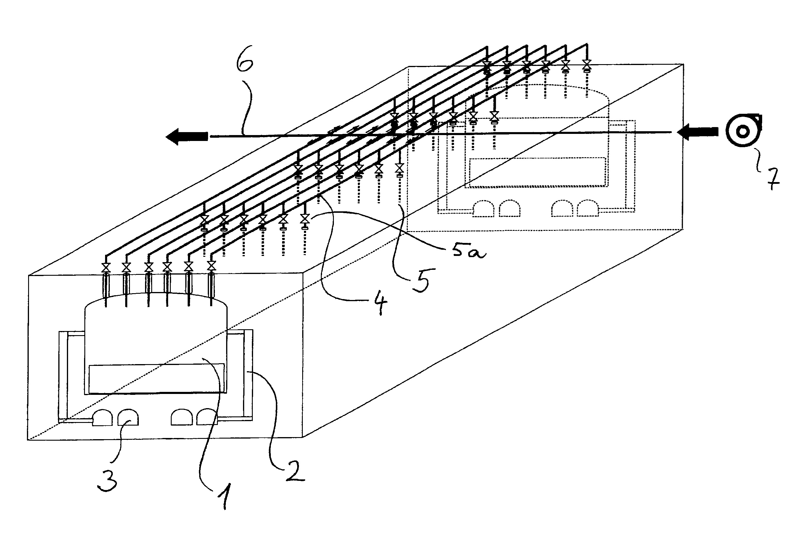
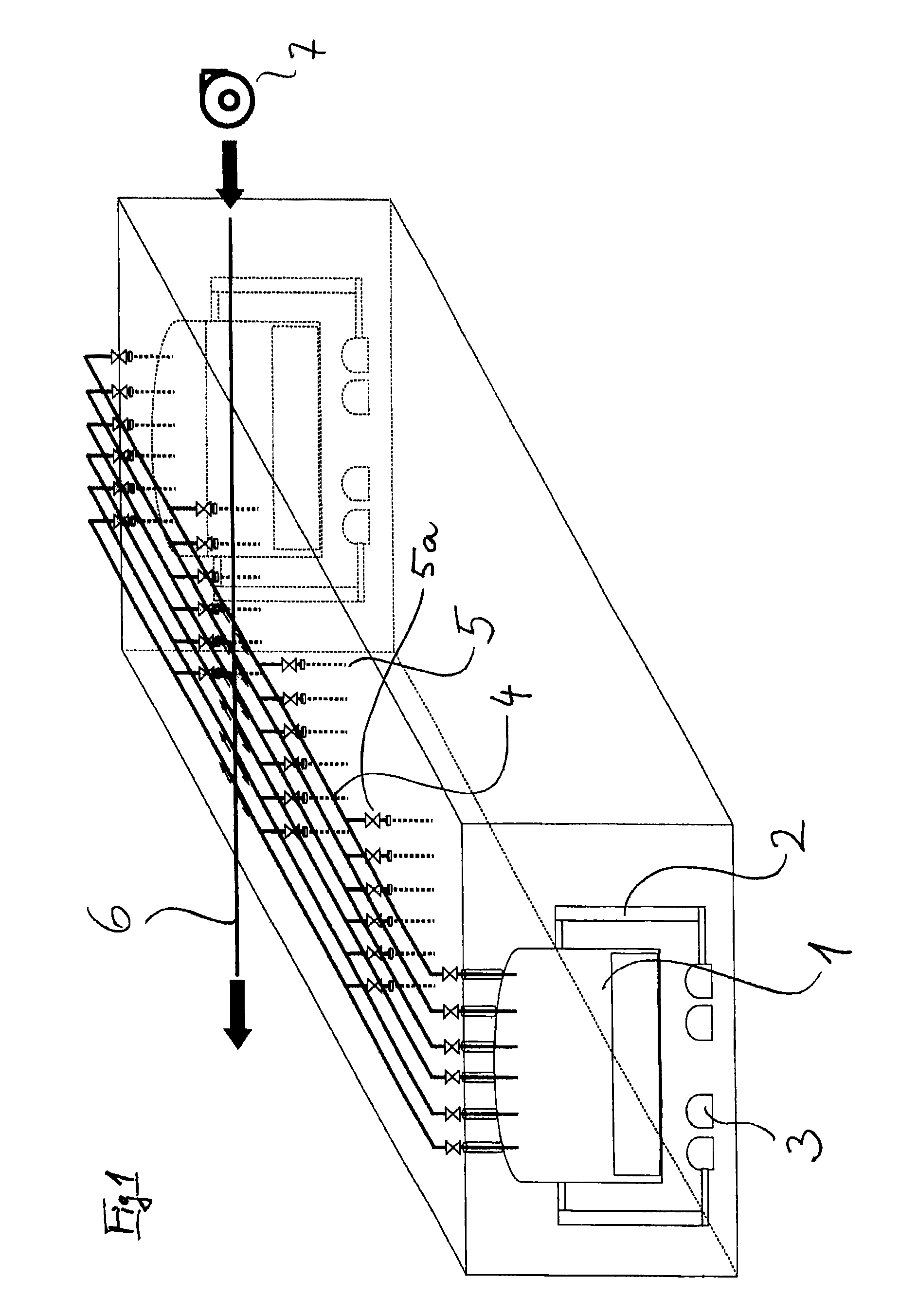
[0013]The attached diagrams and charts serve to illustrate the said system, FIG. 1 showing a schematic and perspective view of the coking chamber, using the Heat- Recovery process, with coke filling opening 1, downcomer system 2 and ducts 3 arranged underneath and required to evacuate the combustion gases, and the said ducts 3 may be equipped with internal post-combustion devices.

[0014]The system arranged above the coking chamber consists of feed lines 4, each being connected with a plurality of feed openings 5. The said feed lines 4 are connected to a common header system 6, which is slightly pressurised by means of a blower 7. At least one control device 5a is installed between the common air supply header system 6 and the individual feed openings 5.

LIST OF REFERENCE DESIGNATIONS

[0015]1 Coke filling opening[0016]2 Downcomer system[0017]3 Ducts[0018]4 Feed lines[0019]5 Feed openings[0020]5a Control Device of Feed Openings[0021]6 Collecting system[0022]7 Blowers


PUM


Abstract

Device for burning coking gas in a coking chamber of a coke oven of the “non-recovery type” or “heat-recovery type”, a multiplicity of inlet openings for primary air being arranged in the roof of each oven chamber in such a way that the coking gas produced during the coking is brought into uniform contact with the desired quantity of primary air for the partial combustion of the coking gas, these inlet openings for primary air being combined above the oven for each chamber separately by an air feed system, the air feed systems of the individual oven chambers being connected to an air feed system common to many oven chambers, and a respective control member for varying the primary air quantity over the carbonizing time being provided between the common air feed system and the air feeds of the individual oven chambers. A slight, constant positive pressure can be applied to the common air feed system.

Description

BACKGROUND OF THE INVENTION[0001]The invention relates to a device and a process for feeding combustion air required to burn coking gas that is released above the coal bed when coal is coked in coking plants with coking chambers, using the Non-Recovery process or Heat-Recovery process. The process described in this application is independent of the number of coke ovens, provided they form a battery. DE 102 01 985 A1, for example, describes a device of this type.[0002]Heat Recovery coke ovens, as a rule, are heated by burning the gas obtained during the coking process. The combustion is controlled in such a manner that part of the gas is burned in the oven chamber above the coal inventory with the aid of primary air. This partly burned gas is conveyed through ducts also named “downcomer” to the heating flues arranged in the sole slab of the oven chamber and subsequently it is completely burned by adding further combustion air also named secondary air.[0003]Hence, this method is used ...

Claims


Application Information

Patent Timeline
IPC IPC(8): C10B47/08C10B47/10C10B21/10
CPCC10B15/02
Inventor KIM, RONALDSCHUECKER, FRANZ-JOSEF
Owner UHDE GMBH
Why Eureka
Try Eureka