Welding apparatus and welding method

a welding apparatus and welding method technology, applied in the direction of soldering apparatus, manufacturing tools,auxillary welding devices, etc., can solve the problems of complex construction of welding guns, difficult to compactly construct welding guns, and second electrode tips

Inactive Publication Date: 2012-10-09
HONDA MOTOR CO LTD
View PDF11 Cites 2 Cited by
  • Summary
  • Abstract
  • Description
  • Claims
  • Application Information

AI Technical Summary

Benefits of technology

[0005]In one or more embodiments of the invention, there are provided a welding apparatus and a welding method in which when a welding target portion of the work is clamped by the first electrode tip and the second electrode tip opposed to each other, even if an obstacle portion such as a hollow portion is formed on the second electrode tip side of the welding target portion, resistance welding can be reliably performed to the welding target portion without needing to offset the second electrode tip from the position opposing the first electrode tip.
[0012]According to the second aspect of the invention, even if the surface of the work against which the both abutment members are abutted is inclined, the both abutment members can be abutted uniformly along the surface of the work. As a result, electrical conduction can be reliably ensured with respect to the work.
[0013]According to the third aspect of the invention, since the both abutment members are brought into pressure contact with the work by the pressurizing means, the both abutment members can be reliably abutted against the work. As a result, it is possible to reliably prevent the adhesion of the abutment members with respect to the work due to an insufficiently abutted state.
[0014]According to the fourth aspect of the invention, in the above-described first welding step, the first electrode tip is abutted against the first welding target portion of the work positioned in the central portion (position in a substantial center) between the both abutment members, and the second electrode tip is abutted against the electrically conductive member in an opposing relation to the first electrode tip. As a result, the respective abutment members are positioned at equal distances from the first electrode tip, so that an electric current flows uniformly between the first electrode tip and the respective one of the abutment members. Hence, it is possible to prevent the concentration of the electric current on either one of the abutment members and prevent the adhesion between each abutment member and the work, and it is possible to satisfactorily form the first weld.
[0015]Next, in the above-described second welding step, the first electrode tip is abutted against the second welding target portion of the work positioned between the first weld and one abutment member, and the second electrode tip is abutted against the electrically conductive member in the opposing relation to the first electrode tip. At this time, the one abutment member is at a position close to the first electrode tip, while the other abutment member is at a position remote from the first electrode tip. However, since a nugget is formed in the first weld due to the above-described first welding step, a smooth flow of electric current has already been ensured. As a result, it is possible to prevent the concentration of the electric current on the one abutment member and prevent the adhesion between the abutment member and the work, and it is possible to satisfactorily form the second weld.
[0016]Subsequently, in the above-described third welding step, the first electrode tip is abutted against the third welding target portion of the work positioned between the first weld and the other abutment member, and the second electrode tip is abutted against the electrically conductive member in the opposing relation to the first electrode tip. In this case as well, the one abutment member is at a position remoter from the first electrode tip than the other abutment member. However, between the first electrode tip and the one abutment member located at the remote position, nuggets have been formed in the first weld through the above-described first welding step and in the second weld through above-described second welding step, so that the flow of electric current has been ensured sufficiently. As a result, it is possible to prevent the concentration of the electric current on the other abutment member and prevent the adhesion between the abutment member and the work, and it is possible to satisfactorily form the third weld.

Problems solved by technology

However, in a case where an obstacle portion such as a hollow portion is formed on the second electrode tip side of the welding target portion of the work, it is impossible to cause the second electrode tip to directly abut against the opposing side of the welding target portion against which the first electrode tip abuts.
Namely, there are drawbacks in that not only does the construction of the welding gun become complex, but it becomes difficult to construct the welding gun compactly.

Method used


Image

  • Welding apparatus and welding method
  • Welding apparatus and welding method
  • Welding apparatus and welding method

Examples


Embodiment Construction

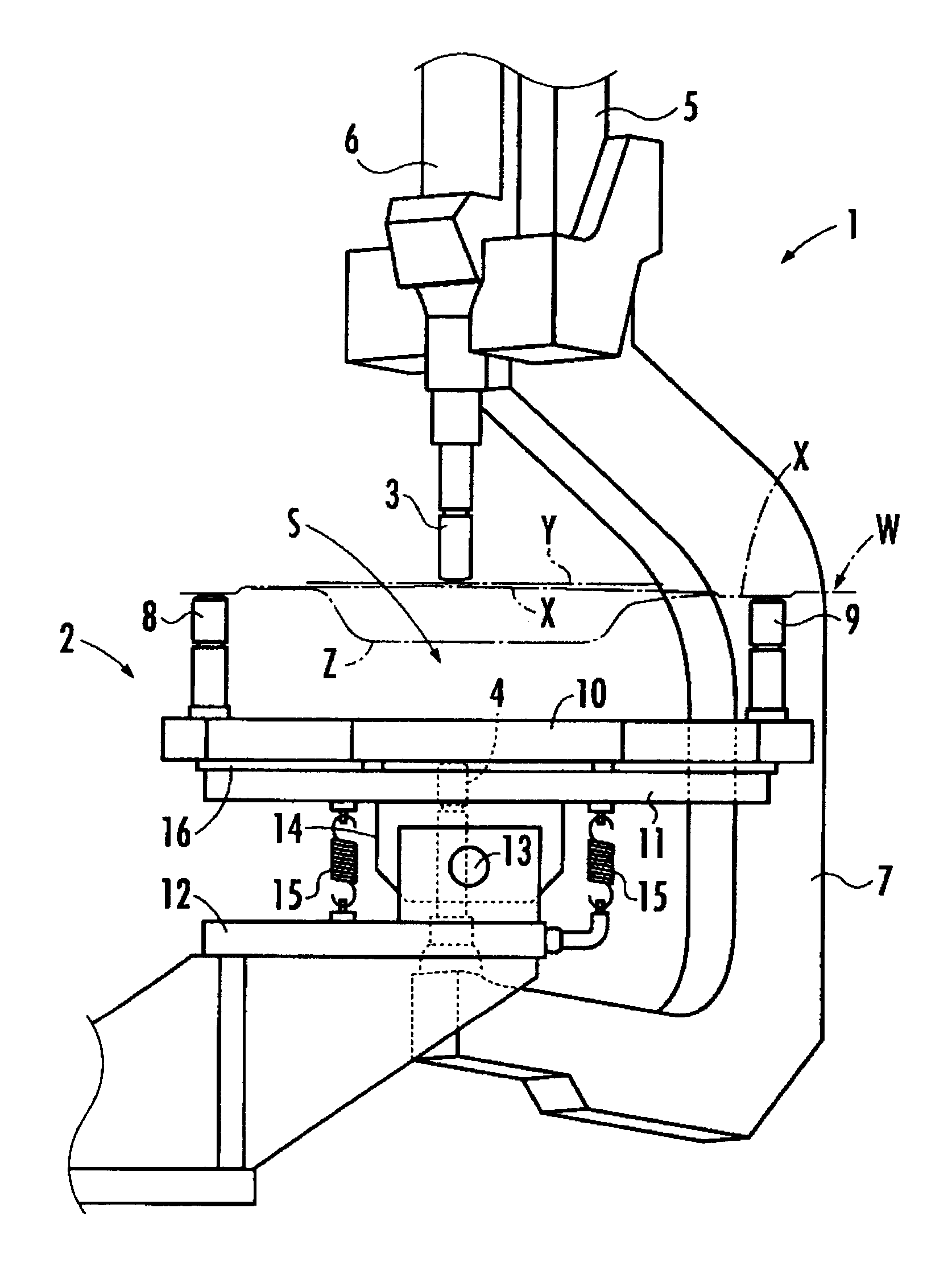
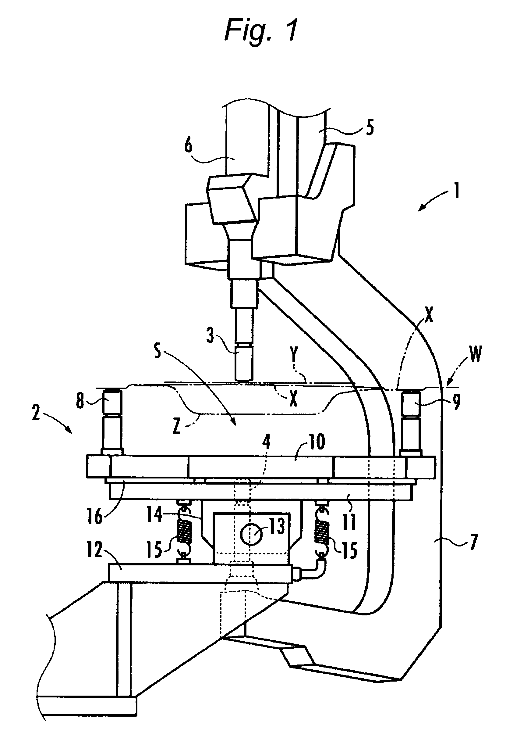
[0024]A description of an embodiment of the present invention will be given on the basis of drawings. FIG. 1 is an explanatory diagram illustrating a construction of essential portions of a welding apparatus in accordance with the embodiment. FIG. 2 is an explanatory cross-sectional view of the welding apparatus in accordance with the embodiment. FIGS. 3A to 3D are explanatory diagrams illustrating a welding operation using the welding apparatus in accordance with the embodiment.

[0025]As shown in FIGS. 1 and 2, the welding apparatus in accordance with a exemplary embodiment of the invention is constituted by a welding gun 1 and an electrically conductive part 2. It should be noted that a work W which is subjected to welding in the embodiment is one in which another panel part Y is superposed on an upper surface side of a panel part X serving as a base, and the panel part X integrally has a hollow portion Z on its lower side. The welding apparatus in accordance with the embodiment we...


PUM

PropertyMeasurementUnit
electrical conductionaaaaaaaaaa
conductiveaaaaaaaaaa
electrically conductiveaaaaaaaaaa

Abstract

A welding apparatus includes a first electrode tip; a second electrode tip opposing the first electrode tip; and an electrically conductive part which is provided so as to be freely interposed between the second electrode tip and a work and ensures electrical conduction between the second electrode tip and the work when the electrically conductive part is interposed between the second electrode tip and the work, the electrically conductive part including an electrically conductive member one side of which opposes the work with a presence of a void space from the work when the electrically conductive member is interposed between the second electrode tip and the work, and against which the second electrode tip is abutted on another side thereof, and a pair of electrically conductive abutment members which are provided integrally with the electrically conductive member in such a manner as to extend toward the work, and distal ends of which are abutted against the work, a position of abutment of the electrically conductive member against the second electrode tip being positioned between the pair of abutment members.

Description

TECHNICAL FIELD[0001]The present invention relates to a welding apparatus and a welding method for performing resistance welding by clamping a welding target portion of a work by a first electrode tip and a second electrode tip opposed to each other.BACKGROUND ART[0002]For instance, when a vehicle body of an automobile is manufactured, it is practiced to superpose a plurality of panel parts or the like, which are works, and to perform welding. In this type of welding, the use of a so-called welding gun is conventionally known which has a first electrode tip and a second electrode tip opposing the first electrode tip, whereby a welding target portion of a work is clamped in a pressurized state by the first electrode tip and the second electrode tip, and resistance welding is performed for the welding target portion (e.g., refer to JP-A-11-47944).[0003]However, in a case where an obstacle portion such as a hollow portion is formed on the second electrode tip side of the welding target...

Claims


Application Information

Patent Timeline
Patent Type & Authority Patents(United States)
IPC IPC(8): B23K11/24
CPCB23K11/11B23K11/115
Inventor KITAGAWA, JUNHORIMUKAI, TOSHIYUKITANABE, JUNYAOYAMA, SHINYAUCHIYAMA, KAZUNAO
Owner HONDA MOTOR CO LTD
Why Eureka
Try Eureka