
Object recognition apparatus utilizing beam scanning for detecting widths of objects of various sizes and located at various ranges

a beam scanning and object technology, applied in the direction of reradiation, distance measurement, instruments, etc., can solve the problems of not being valid, not being able to transmit beams having ideal cut-off characteristics, and the effect of reducing the resolution of beam scanning is more severe, so as to achieve the effect of greater accuracy and reliability of detecting object width

Active Publication Date: 2012-10-09
DENSO CORP
View PDF12 Cites 4 Cited by
  • Summary
  • Abstract
  • Description
  • Claims
  • Application Information

AI Technical Summary

Benefits of technology

The present invention provides an object recognition apparatus that can accurately detect the width of objects using scan beams. The apparatus can transmit scan beams and receive reflected waves from the detected objects, and process the data to estimate the width of each object. The apparatus can also segment the detected objects and extract the width of each segment, even if the objects are at different ranges. The apparatus can provide greater accuracy and reliability in detecting object widths, and can be used in various applications such as autonomous vehicle detection.

Problems solved by technology

However the above equation assumes that there is no overlapping between adjacent beams, whereas in actuality, it is not possible to transmit beams having ideal cut-off characteristics, such as illustrated in FIG. 10A.
As a result, overlapping occurs between adjacent beams, so that the above equation is not actually valid, since the angular resolution of scanning is reduced.
This effect of decreased resolution of beam scanning is more severe for laser light beam scanning than for scanning by millimeter-range electromagnetic waves.
However that method has the following disadvantage.
If the object to be recognized has low reflectivity, then the reflected light from the object may be judged to be scattered light, so that object recognition will not be achieved.
In addition, the following disadvantage occurs in the case of the above method whereby the threshold value is adjusted to restrict the maximum object width that is detected.
A similar disadvantage occurs in the case of the above method whereby the threshold is set as a fixed proportion of the peak value of received-light signal strength corresponding to a detected object.
In that case too, since only a single threshold is utilized, it is not possible to achieve accurate width estimation of a plurality of objects which may be of various widths and / or located at various different distances, and so correspond to a plurality of respectively different peak values of received-light signal strength.

Method used


Image

  • Object recognition apparatus utilizing beam scanning for detecting widths of objects of various sizes and located at various ranges
  • Object recognition apparatus utilizing beam scanning for detecting widths of objects of various sizes and located at various ranges
  • Object recognition apparatus utilizing beam scanning for detecting widths of objects of various sizes and located at various ranges

Examples


Embodiment Construction

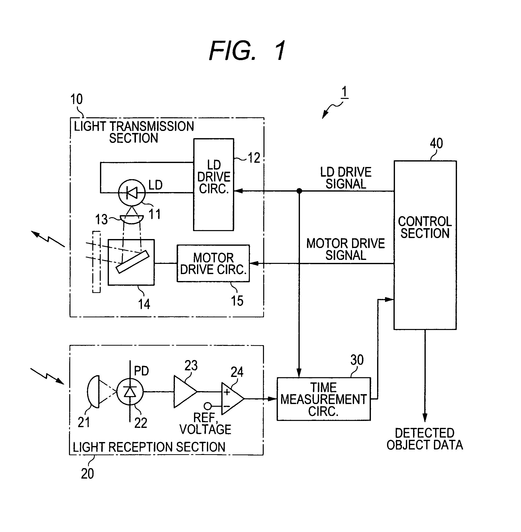
[0046]FIG. 1 is a block diagram showing the overall configuration of an embodiment of an object recognition apparatus, designated by numeral 1, which is installed in a vehicle referred to in the following as the host vehicle. The center of the object recognition apparatus 1 is assumed to be located on a central front / back axis of the host vehicle. The object recognition apparatus 1 serves to detect objects located ahead of the host vehicle and generate object data corresponding to each detected object, with the data specifying the estimated position and width of the object. The detected object data obtained by the object recognition apparatus 1 are supplied to a vehicle control apparatus (not shown in the drawings), for use in generating warning indications to the vehicle driver when a detected object is judged to be within a predetermined warning region. In addition (when the detected object is a candidate preceding vehicle) the detected object data may be applied for intra-vehicle...


PUM


Abstract

An object recognition apparatus performs a sweep of a scanned region by transmitting scanning wave beams at respective scan angles and successive timings, derives a received-wave signal strength value and reflection location corresponding to each scan wave beam during the sweep, and assigns a set of mutually adjacent reflection locations as a segment. A corresponding range value of the segment is calculated, expressing an estimated distance of a detected object. A threshold value is derived in accordance with the segment range, a region of the segment in which the signal strength values exceed the threshold value is extracted, and the width of the extracted region is designated as the width of the detected object.

Description

CROSS-REFERENCE TO RELATED APPLICATIONS[0001]This application is based on and incorporates herein by reference Japanese Patent Application No. 2009-274592 filed on Dec. 2, 2009.BACKGROUND OF THE INVENTION[0002]1. Field of Technology[0003]The present invention relates to an object recognition apparatus installed in a vehicle, which transmits waves within a region ahead of the vehicle for detecting objects located in that region based upon resultant reflected waves, and in particular for detecting the widths of such objects.[0004]2. Description of Related Art[0005]Types of object recognition apparatus for installation in a vehicle (referred to in the following as the host vehicle) are known, whereby laser light beams or beams of millimeter-range radio waves are scanned within a region ahead of the host vehicle, with objects within that regions (in particular, other vehicles) being detected based on resultant received reflected waves. The detection results may be used to generate warni...

Claims


Application Information

Patent Timeline
Patent Type & Authority Patents(United States)
IPC IPC(8): G01C3/08G06K9/46G01S13/93G01S7/497G01S17/931
CPCG01S7/42G01S17/936G01S17/931
Inventor BEPPU, TAROTAKAGI, KIYOKAZUOGAWA, TAKASHIHAZUMI, HIROSHI
Owner DENSO CORP
Learn More