
In-line duct supplemental heating and cooling device and method

a technology of heating and cooling devices and in-line ducts, which is applied in the direction of heating types, instruments, static/dynamic balance measurement, etc., can solve the problems of not being able to individually activate and deactivate devices, types of devices are not able to also assist in cooling the room, and are difficult to heat, so as to prevent overheating of heater air or increase air circulation. , the effect of reducing the difficulty of heating

Active Publication Date: 2012-10-09
TPI A TN
View PDF48 Cites 13 Cited by
  • Summary
  • Abstract
  • Description
  • Claims
  • Application Information

AI Technical Summary

Benefits of technology

"The present invention provides an electric heating and cooling device that can be added to a standard furnace system to supplement the heating and cooling of a room. The device includes an electric heater, a fan, and a housing for containing the heater and fan. The device is connected to an air duct and is controlled by a thermostat that selects the desired temperature in the room. The device automatically activates and deactivates based on the thermostat and the air discharged from the duct. The device also includes a discharge air temperature sensor and a safety temperature limit switch to prevent overheating. The device can be installed in a gap in the air duct and includes a control board, conduit for wiring, and a vibration insulator sleeve for reducing sound and vibration. The method of using the device includes selectively adjusting the thermostat and detecting the temperature in the room. The device can be deactivated when the desired temperature is reached, and the method includes deactivating the fan when the desired temperature is higher than the desired temperature."

Problems solved by technology

However, some of these types of devices must be manually activated and deactivated.
Even if such a device is adapted to be activated automatically, the components of the device, such as a heater or a fan, etc., are typically not adapted to be activated and deactivated individually.
Further, these types of devices are not adapted to also assist in cooling the room when the temperature in the room is warmer than desired.
Additionally, with respect to devices adapted to be mounted in an air duct, several safety issues and fire hazards can arise, such as overheating of the air in the duct or of the heating device itself.

Method used


Image

  • In-line duct supplemental heating and cooling device and method
  • In-line duct supplemental heating and cooling device and method
  • In-line duct supplemental heating and cooling device and method

Examples


Embodiment Construction

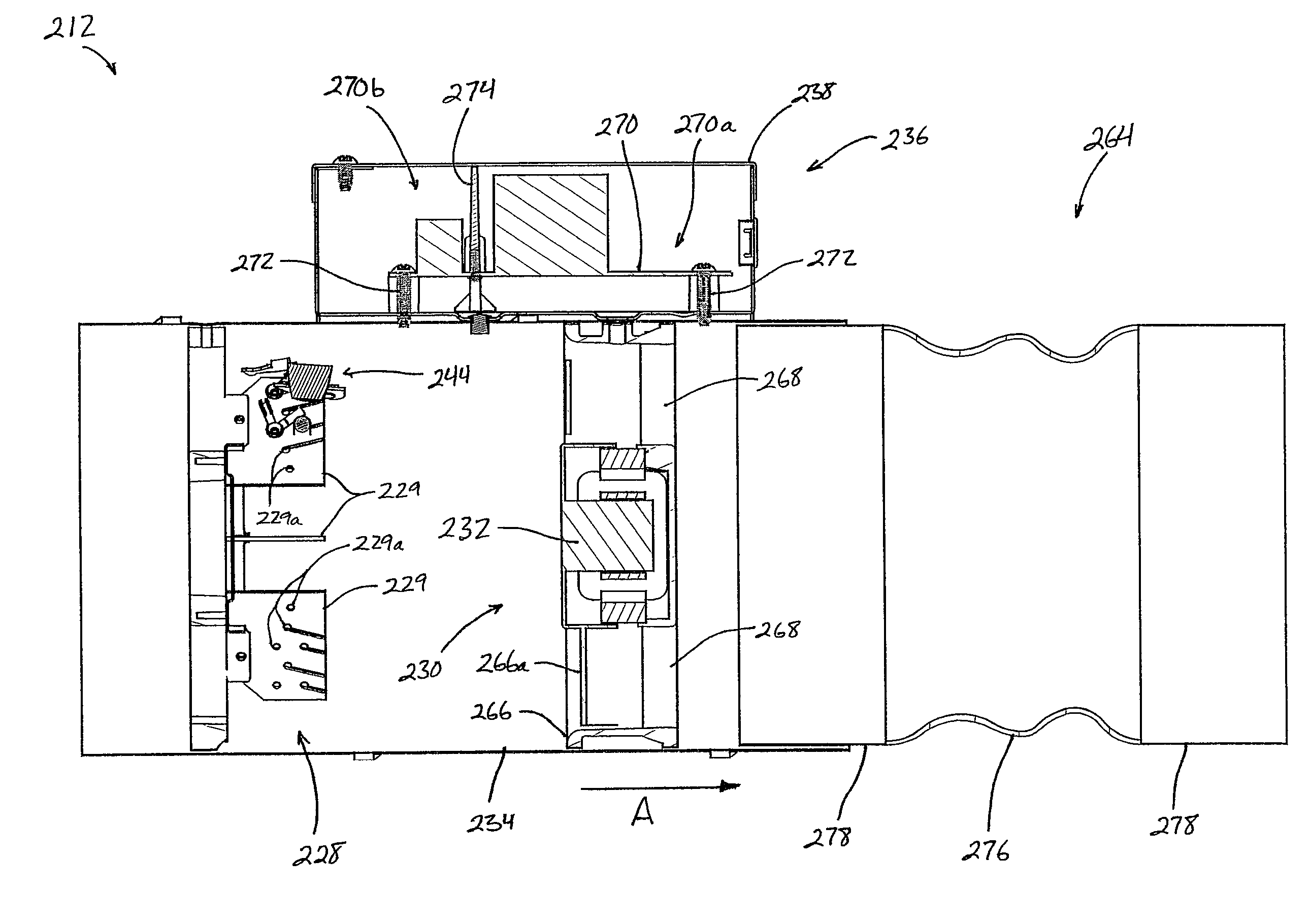
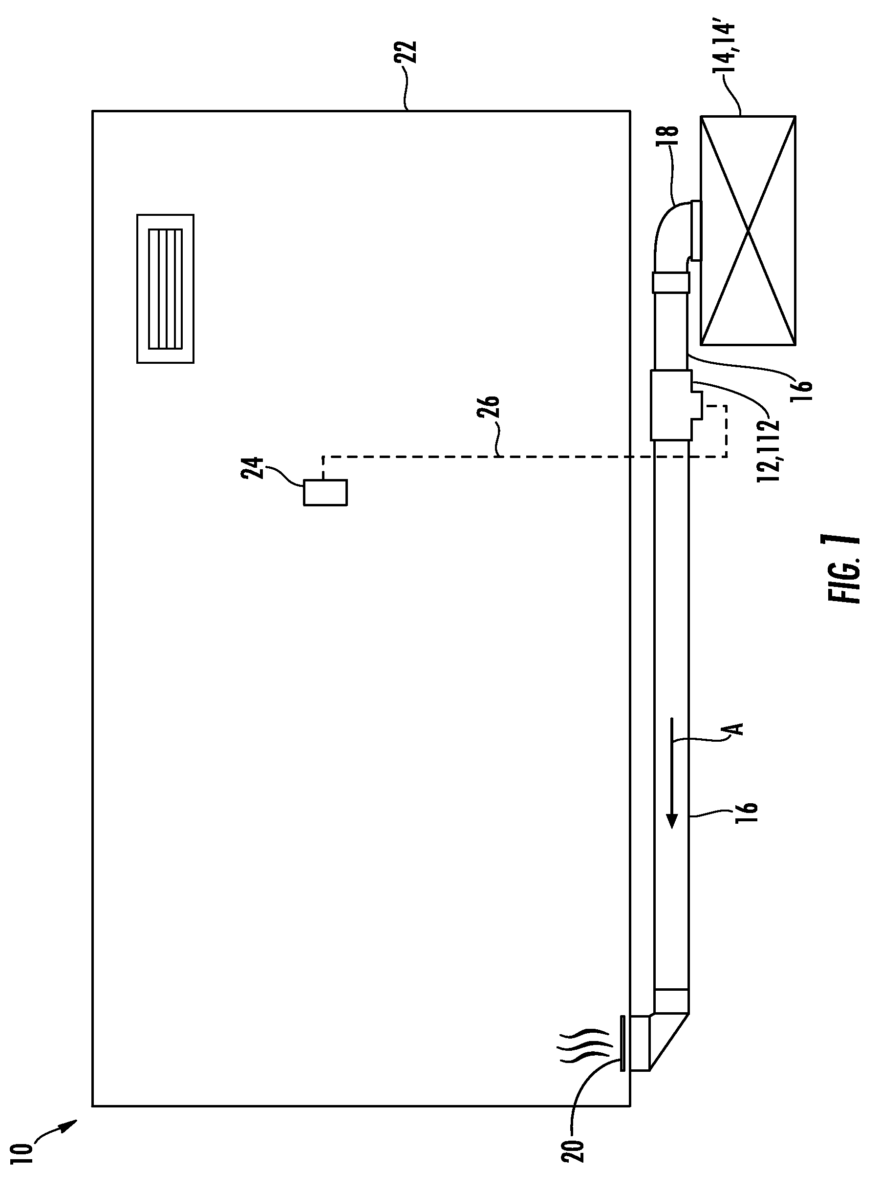
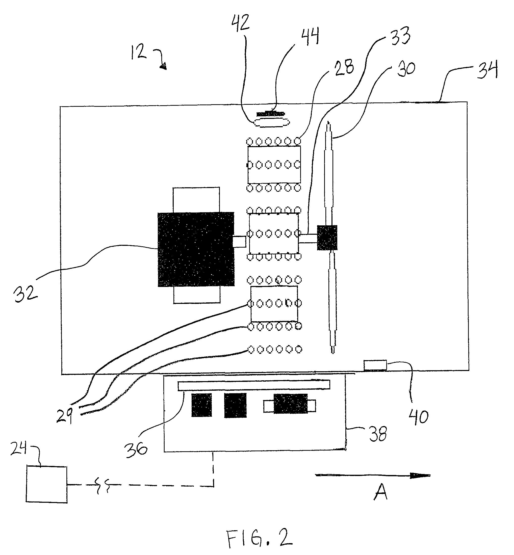
[0028]Referring now to the drawings and the embodiments illustrated therein, a system 10 for heating and cooling or conditioning a space, such as a room in a home or other building, includes an electric heating and cooling device 12 adapted to supplement a traditional or standard furnace 14 or air conditioner 14′ (FIG. 1). Heating and cooling device 12 is adapted to be at least partially mounted in an air duct, such as air duct 16 of a forced air duct system, which extends from furnace 14 or a cooling unit 14′ for transferring heated or cooled air to a room 22. Device 12 is especially useful for rooms that may be remote from furnace 14 (or an air conditioning unit 14′ that may be connected to and use duct system 16) at or near the end of duct system 16, where heating and / or cooling is / are less efficient than for rooms closer to furnace 14 and / or cooling unit 14′. Device 12 may also be useful for rooms that are large or that have a number of windows, which may make such rooms difficu...


PUM


Abstract

An inline duct supplemental heating and cooling device provides heated and / or cooled air to a room in a building to supplement the heating provided by the existing furnace or the cooling provided by the existing cooling unit in the building. The device includes an electric heater and fan that are activated and deactivated individually by a controller, which receives room temperature data from a thermostat. The device may include one or more separate safety devices to prevent overheating of heater air or of the device itself. Optionally, a vibration-insulating sleeve may be used to couple the device to an existing ventilation duct of the building.

Description

CROSS REFERENCE TO RELATED APPLICATION[0001]The present invention claims the benefit of U.S. provisional application Ser. No. 60 / 970,102, filed Sep. 5, 2007, which is hereby incorporated herein by reference in its entirety.FIELD OF THE INVENTION[0002]The present invention relates generally to supplemental heating and cooling devices, especially for forced air heating or cooling systems in buildings.BACKGROUND OF THE INVENTION[0003]It is known to provide auxiliary or supplemental heating devices in rooms that tend to be cooler than the rest of a home or building, or in rooms in which a higher temperature is desired. Such supplemental heaters may be placed directly in the room or may be positioned in an air duct that is adapted to supply heat from the home's standard or traditional furnace to the room.[0004]However, some of these types of devices must be manually activated and deactivated. Even if such a device is adapted to be activated automatically, the components of the device, su...

Claims


Application Information

Patent Timeline
Patent Type & Authority Patents(United States)
IPC IPC(8): F24D13/00F24F1/0007F24F11/76
CPCF24F1/0007F24D5/02F24H3/0411F24D13/04F24D19/1084G05D23/1902F24F11/04F24H9/2071F24F11/0076F24F11/053F24D19/1096F24F11/0012F24F11/30F24F2110/10F24F11/70F24F11/74F24F11/76F24F11/56F24F11/88F24F11/33
Inventor MULDER, ERIC P
Owner TPI A TN
Learn More