Damping force control apparatus for vehicle

a control apparatus and vehicle technology, applied in the direction of brake systems, cycle equipments, instruments, etc., can solve the problems of adversely affecting the maneuvering stability of the vehicle, unnecessary vibration in the vehicle body, etc., and achieve satisfactory maneuvering stability and rapid maneuvering

Inactive Publication Date: 2012-10-09
TOYOTA JIDOSHA KK
View PDF15 Cites 5 Cited by
  • Summary
  • Abstract
  • Description
  • Claims
  • Application Information

AI Technical Summary

Benefits of technology

[0006]Incidentally, it is generally said that, in order to secure maneuvering stability during turning of the vehicle, the timing of generation of a roll and that of a pitch are desired to be synchronized, as taught in Patent Document 1. Further, it is said that the vehicle is desired to have a pitch angle such that the front of the vehicle slightly descends. Moreover, in general, when a vehicle turns, as taught in Patent Documents 2 and 3, damping forces of shock absorbers disposed on the inner side of a turning locus of the center of the vehicle (hereinafter simply referred to as the “turn-locus inner side”) are increased, and damping forces of shock absorbers disposed on the outer side of the turning locus (hereinafter simply referred to as the “turn-locus outer side”) are decreased, whereby the posture of the vehicle is controlled so as to lower a sprung portion (the vehicle body).
[0008]The present invention has been achieved to solve the above problems, and an object of the invention is to provide a damping force control apparatus for a vehicle which can quickly converge a change in the posture of the vehicle during a turn due to input of a road surface disturbance, to thereby secure satisfactory maneuvering stability.
[0020]By virtue of the above configuration, it is possible to considerably accurately determine damping forces which must be generated by the shock absorbers disposed on the turn-locus inner side and the shock absorbers disposed on the turn-locus outer side in order to control the roll while synchronizing the phases of the actual roll angle and the actual pitch angle of the vehicle body. Further, through addition and subtraction of the distribution amount which is proportional to the predetermined physical quantity, it becomes possible to maintain a state in which the damping forces of the shock absorbers disposed on the turn-locus inner side are greater than the damping forces of the shock absorbers disposed on the turn-locus outer side (i.e., maintain a proper rolled state), while generating the total demanded damping force which is demanded for the left and right absorbers disposed on the front wheel side in order to control the roll. Accordingly, the roll can be controlled more accurately by making constant the posture changing behavior of the vehicle during a turn, whereby the maneuvering stability of the vehicle can be improved greatly.
[0023]According, when the vehicle body is moving vertically as a result of input of a road surface disturbance, the unnecessary vertical movement of the vehicle body can be damped quickly by correcting the total damping force, required to control the roll, in consideration of the vibration-suppressing damping force (through addition or subtraction of the vibration-suppressing damping force). As a result, satisfactory maneuvering stability can be secured.

Problems solved by technology

However, if a force is input to the vehicle body of a vehicle due to a bump or depression on a road surface (disturbance from the road surface (hereinafter referred to as a “road surface disturbance”)) when the vehicle turns in a state in which the damping forces of shock absorbers disposed on the turn-locus inner side are increased, and the damping forces of shock absorbers disposed on the turn-locus outer side are decreased as disclosed in Patent Documents 2 and 3, an unnecessary vibration is generated in the vehicle body.
In particular, since the damping forces of the shock absorbers disposed on the turn-locus outer side are small, these shock absorbers cannot quickly converge the generated vibration, which may adversely affect the maneuvering stability of the vehicle.

Method used


Image

  • Damping force control apparatus for vehicle
  • Damping force control apparatus for vehicle
  • Damping force control apparatus for vehicle

Examples


first embodiment

a. First Embodiment

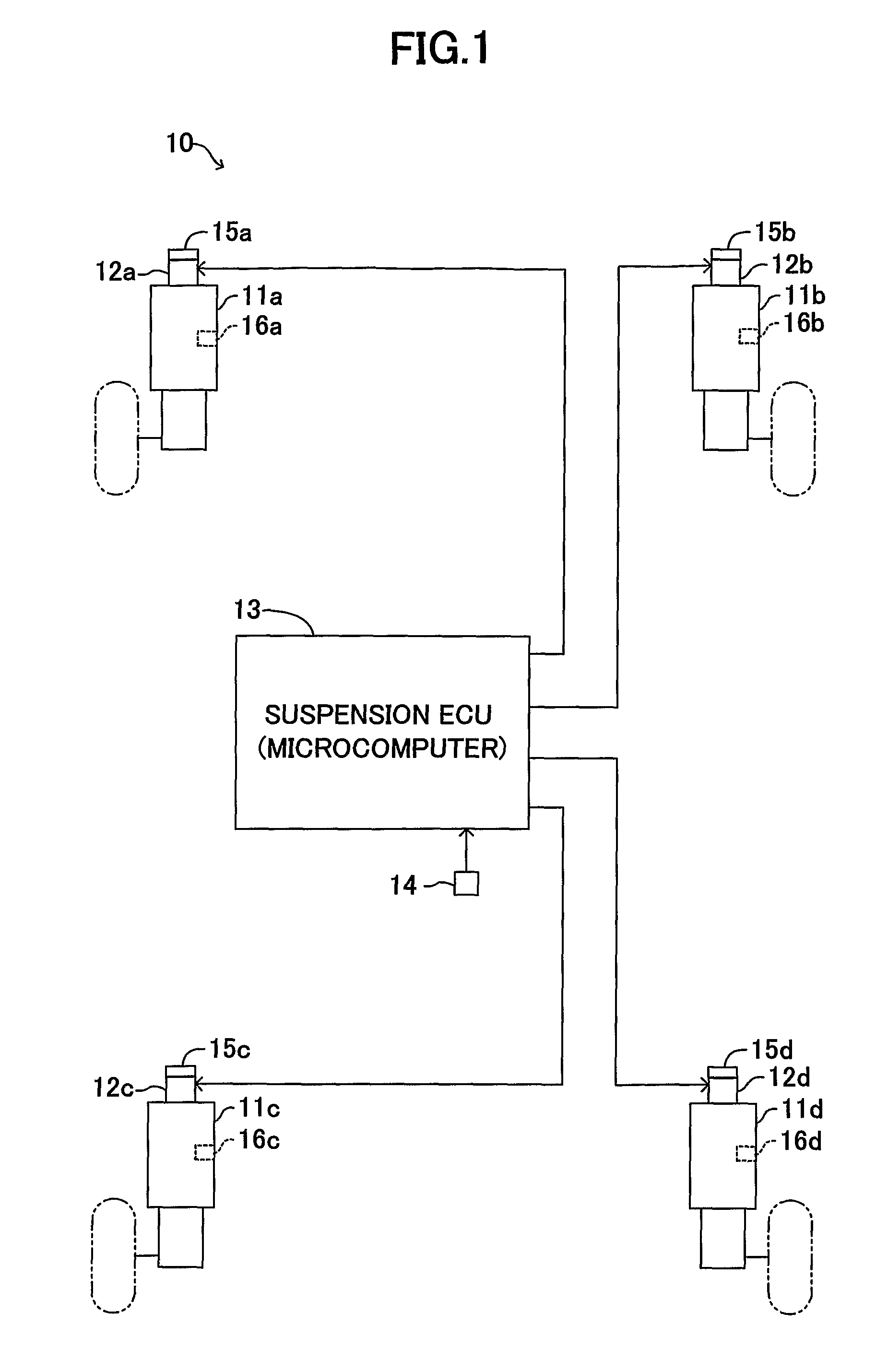
[0031]A damping force control apparatus for a vehicle (hereinafter referred to as a “vehicular damping force control apparatus”) according to an embodiment of the present embodiment will now be described in detail with reference to the drawings. FIG. 1 schematically shows the configuration of a vehicular damping force control apparatus 10 common among embodiments of the present invention. This vehicular damping force control apparatus 10 includes shock absorbers 11a, 11b, 11c, and 11d which connect a vehicle body and wheels (left and right front wheels and left and right rear wheels) of the vehicle.

[0032]The shock absorbers 11a, 11b, 11c, and 11d include rotary valves (electrical actuators) 12a, 12b, 12c, and 12d, each of which changes seamlessly, for example, the diameter of a flow path for working fluid (oil, high-pressure gas, etc.). Although detailed description will be omitted, each of the rotary valves 12a, 12b, 12c, and 12d includes an unillustrated electri...

second embodiment

b. Second Embodiment

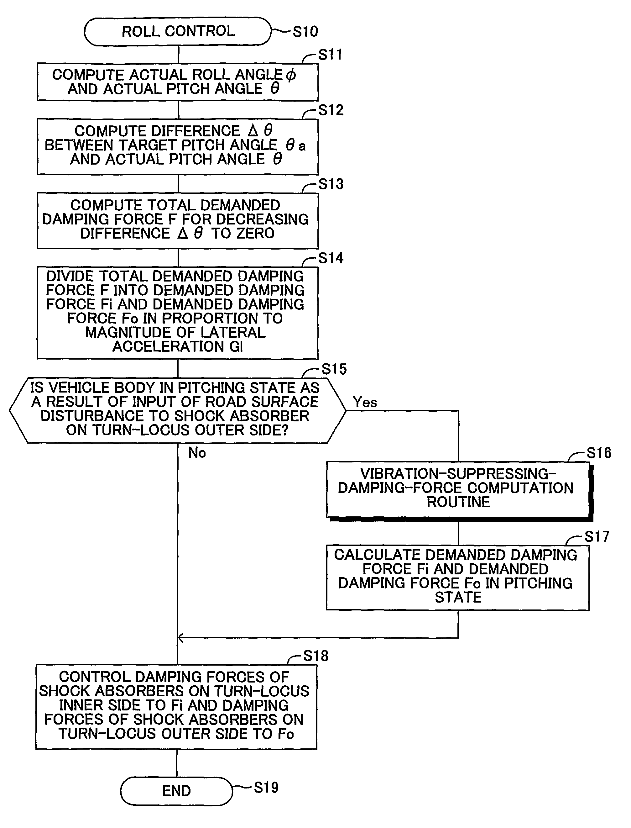
[0086]In the above-described first embodiment, description was provided for the case where the vehicle body is in the pitching state as a result of input of a road surface disturbance only to the shock absorbers 11b and 11d (or the shock absorbers 11a and 11c) on the turn-locus outer side to which the smaller damping force Fo is distributed in a state where the total demanded damping force F is distributed based on the distribution amount X which is proportional to the lateral acceleration Gl. In this case, the demanded damping force Fo of the shock absorbers 11b and 11d (or the shock absorbers 11a and 11c) on the turn-locus outer side is set to be the vibration-suppressing damping force Fz, and the demanded damping force Fi of the shock absorbers 11a and 11c (or the shock absorbers 11b and 11d) on the turn-locus inner side is determined by subtracting the vibration-suppressing damping force Fz from the total demanded damping force F. Thus, the shock absorbers 11...


PUM


Abstract

A suspension ECU computes an actual roll angle and an actual pitch angle of a vehicle, and computes a difference between a target pitch angle and the actual pitch angle. The ECU then computes a total demanded damping force which must be cooperatively generated by shock absorbers so as to decrease the computed difference to zero, and distributes the total demanded damping force in proportion to the magnitude of a lateral acceleration such that a demanded damping force on the turn-locus inner side becomes greater than a demanded damping force on the turn-locus outer side. Further, the ECU determines whether or not the vehicle body is vibrating in the vertical direction as a result of input of a road surface disturbance, calculates a vibration-suppressing damping force needed for damping the vibration, and determines the demanded damping forces by use of the vibration-suppressing damping force.

Description

TECHNICAL FIELD[0001]The present invention relates to a damping force control apparatus for a vehicle which changes and controls damping forces of shock absorbers disposed between the vehicle body and wheels.BACKGROUND ART[0002]There have actively been proposed apparatuses and methods which change and control damping forces of shock absorbers disposed between the vehicle body and wheels. For example, Japanese Patent Application Laid-Open (kokai) No. 2007-8373 (Patent Document 1) discloses a suspension-characteristic computation method which provides a design index of a suspension in consideration of the correlation between roll and pitch generated in the vehicle body. In this suspension-characteristic computation method, a pitch moment determined by the geometries of suspensions is computed as the sum of a front-wheel-side ascending / descending force and a rear-wheel-side ascending / descending force. The front-wheel-side ascending / descending force is represented by the product of a fr...

Claims


Application Information

Patent Timeline
Patent Type & Authority Patents(United States)
IPC IPC(8): B60G17/00
CPCB60G17/0162B60G17/0165B60G17/08B60G2400/0511B60G2400/0512B60G2400/0523B60G2400/102B60G2400/104B60G2400/252B60G2400/41B60G2400/91B60G2500/104B60G2600/184B60G2800/012B60G2800/014B60G2800/162B60G2800/164B60G2800/24B60G2800/91
Inventor IYODA, IKUHIDEHONMA, MOTOHIKO
Owner TOYOTA JIDOSHA KK
Why Eureka
Try Eureka