Electronic archery sighting system and bore sighting arrow

a sighting system and electronic technology, applied in the field of electronic sighting, can solve the problems of increasing archer fatigue, reducing shot accuracy, reducing accuracy and ultimately replacement of sight, and achieve the effect of improving shot accuracy

Inactive Publication Date: 2012-10-16
NOCKOUT OUTDOORS LLC
View PDF53 Cites 13 Cited by
  • Summary
  • Abstract
  • Description
  • Claims
  • Application Information

AI Technical Summary

Benefits of technology

[0006]The archery sighting system solves several problems for archers by combining existing technologies into a single sighting system to improve shot accuracy. In some exemplary embodiments, the system captures the shot on digital video. One embodiment includes a range finder with slope detect technology to aid the archer in selecting the proper distance to the target even with inclined and declined topography. In another exemplary embodiment, a chronograph determines the speed of the arrow (e.g., in feet per second) to help tune the bow automatically. In additional embodiments, a display of the sighting system includes touch screen capabilities and electroluminescent technology to allow the archer to see-through the display. The display automatically adjusts an electronic dot based on the speed of the bow and the distance to the target. A digital camera with zoom capabilities captures video footage of the shot. The arrow for the sighting system includes a forward-mounted laser to illuminate the target with a built in 3-axis accelerometer to automatically turn the arrow on and off. The rear section of the arrow or (nock) illuminates after the shot to aid the archer in retrieving the arrow. In some embodiments, the rear facing LED also includes an IR transmitter to wirelessly send the flight information back to a separate receiver. The hunting blades can be removed to allow the archer to use the sighting system for practice, 3D / traditional archery tournaments, and small game hunting.

Problems solved by technology

Unfortunately, modern sights have several drawbacks.
For example, they are often heavy mechanical devices that weigh down the bow and increase archer fatigue, which may decrease shot accuracy over time.
In addition, fiber optic pins often bend or break, resulting in decreased accuracy and ultimately replacement of the sight.
Moreover, even upon making a great shot, an archer often has difficulty locating the arrow.

Method used


Image

  • Electronic archery sighting system and bore sighting arrow
  • Electronic archery sighting system and bore sighting arrow
  • Electronic archery sighting system and bore sighting arrow

Examples


Embodiment Construction

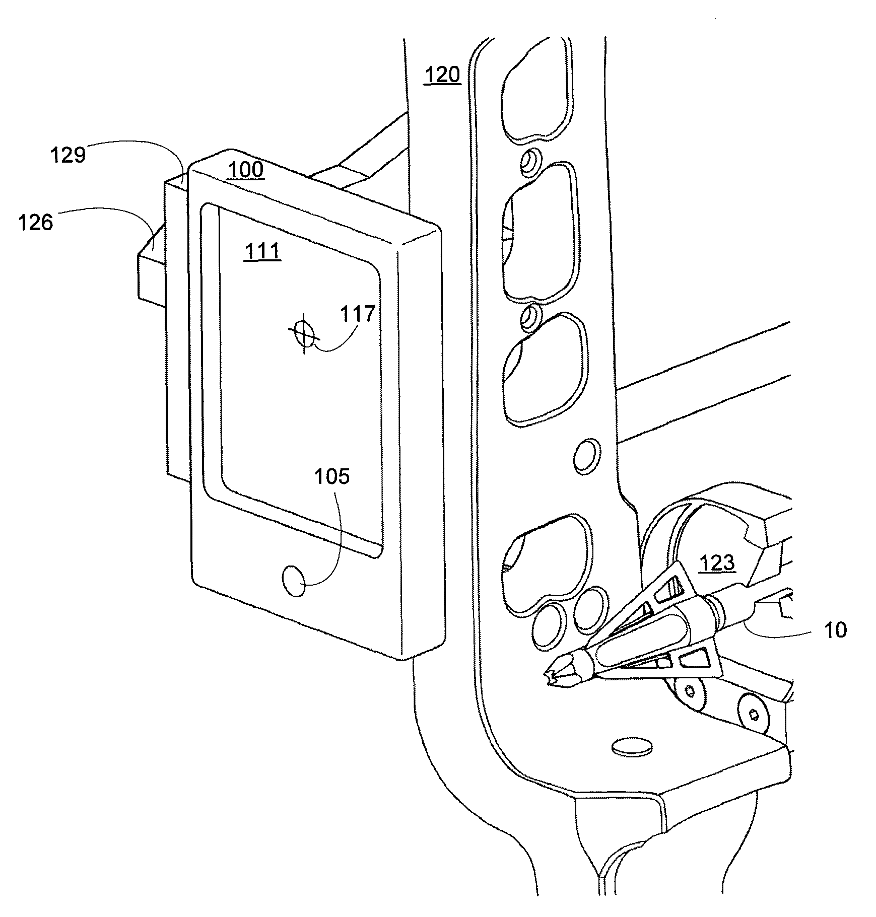
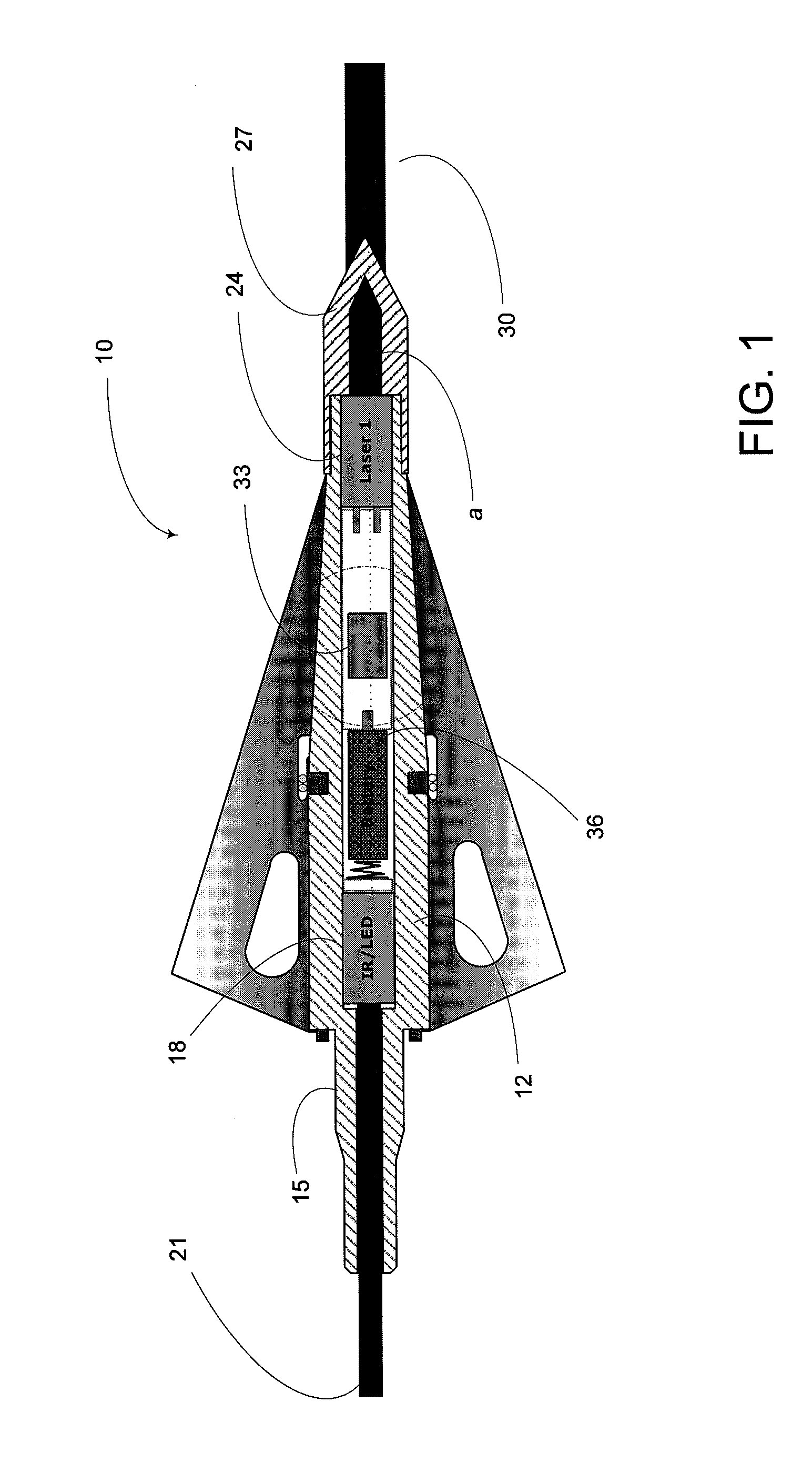
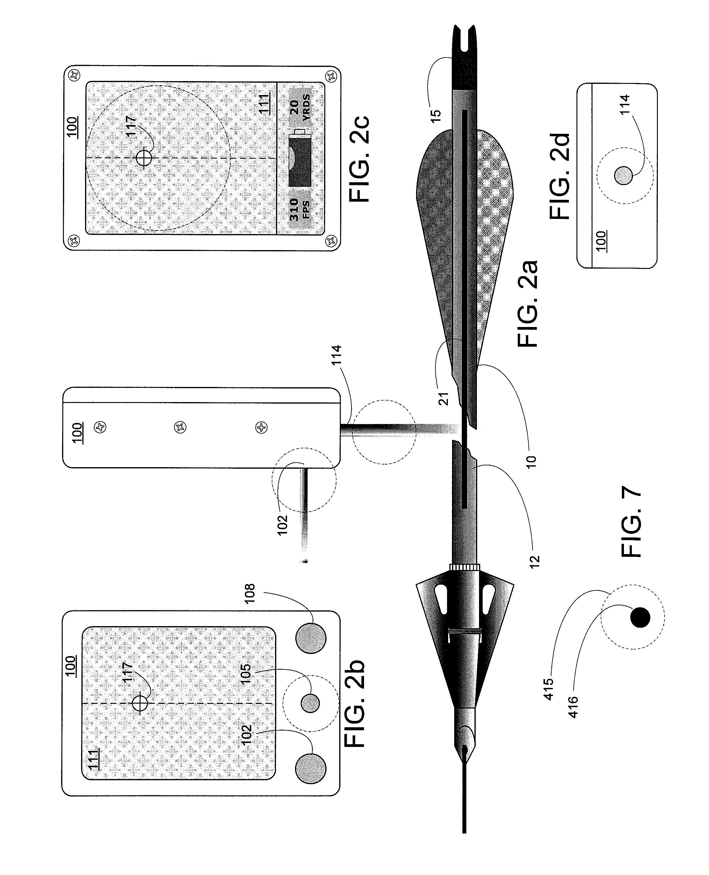
[0022]An archery sighting system is described herein that provides an electronic adjustable sighting device as well as technology that can be included in an arrow to improve shot accuracy and arrow / target recovery. Throughout this application, reference is made to the sport of archery and this sighting system is described to include a bow and an arrow. There is nothing that limits the use of the sighting system to archery applications. It is envisioned that, for example, the same system might be used to aim a rifle or handgun; automatic weaponry, such as an automatic rifle; or even a cross-bow. The archery example has been selected as a non-limiting means of explaining more universal principles that are shared in use on any ballistic weapon. For example, the relation of the mount to the sighting system and thus to the weapon is the same whether the weapon is a black-powder rifle or, as here, a bow. Bore-sighting is, likewise, bore-sighting whether on a rifle or, as here, on a bow. T...


PUM


Abstract

An archery sighting system and method for placing a reticule on a display. The system includes a housing mounted in fixed relation to a bow. The housing includes a rangefinder to generate a target distance signal indicative of a target distance between the bow and a target. A display is configured to depict a reticule. A chronograph generates a bow speed indicating a bow speed at which an arrow leaves the bow. A processor receives a bow speed signal from the chronograph, a range signal from the rangefinder. In response to the signals, the processor generates a reticule pattern on the display, the reticule is positioned to indicate an attitude of the bow necessary for an arrow released from the bow at the bow speed to strike a target at the target distance.

Description

PRIORITY CLAIM AND RELATED APPLICATION[0001]This application claims priority to commonly co-owned provisional application Ser. No. 61 / 168,105 filed on Apr. 9, 2009, which is hereby incorporated by reference. Additionally, an arrow suitable for use with the present electronic archery sight is provided in the co-owned, co-pending U.S. patent application Ser. No. 12 / 757,401, entitled, “Arrowhead With Laser”, the entire disclosure of which is hereby incorporated by reference.FIELD OF THE INVENTION[0002]This invention relates generally to archery sighting technology and, more specifically, to electronic sighting.BACKGROUND OF THE INVENTION[0003]Archery sights today typically include a mechanical device mounted on a bow that has one or more pins that an archer looks across at a target to properly aim the bow. Sometimes the pins include an optic fiber that illuminates to make the pin stand out in the archer's view. In addition, some sights include a peep sight mounted to the bowstring that...

Claims


Application Information

Patent Timeline
Patent Type & Authority Patents(United States)
IPC IPC(8): G06F19/00G06G7/80
CPCF41G1/35F41G1/467
Inventor BAY, LARRY
Owner NOCKOUT OUTDOORS LLC
Why Eureka
Try Eureka