Recording apparatus

a recording head and recording technology, applied in the field of recording head, can solve the problems of less simplified hardware configuration of the related art, increased production cost, and reduced efficiency of the recording head, and achieve the effects of moving the recording head, high precision, and moving the recording head

Active Publication Date: 2012-10-16
SEIKO EPSON CORP
View PDF3 Cites 2 Cited by
  • Summary
  • Abstract
  • Description
  • Claims
  • Application Information

AI Technical Summary

Benefits of technology

[0012]In other words, since a recording apparatus according to the second aspect of the invention described above is provided with the controlling section, it is possible to calculate a correction value on the basis of a difference between the theoretical value of driving amount of the driving mechanism and the actual value of driving amount for one driving operation that is performed by the driving mechanism after causing or as a result of causing the recording head to move from the one end in the movement range in which the recording head moves in a direction toward a recording target medium or away from the recording target medium to the other end in the movement range. Then, when a distance from the recording head to a recording target medium is changed through the operation of the driving mechanism, it is possible to drive the driving mechanism with the addition of the calculated correction value. Thus, a recording apparatus according to the second aspect of the invention described above offers the same advantageous effects as those offered by a recording apparatus according to the first aspect of the invention described above. It is preferable to perform the calculation of the correction value at each time when a recording apparatus according to the second aspect of the invention is powered ON. With such a preferred configuration, it is possible to cope with a change with passage of time. In addition, it is possible to compensate variations in precision, which differs from the parts / members / components of one recording apparatus to another.
[0013]In the configuration of a recording apparatus according to the second aspect of the invention described above, it is preferable that, if the direction of the movement of the recording head at the time of the start of current movement operation when changing a distance from the recording head to a recording target medium is different from the direction of the movement of the recording head at the time of the completion of the last change of the distance, the controlling section should make the determination on the basis of the reference driving amount and drive the driving mechanism, which constitutes a third preferred mode of the invention. In addition to the advantageous effects of the invention offered by a recording apparatus according to the second aspect of the invention, a recording apparatus according to the third preferred mode of the invention offers the following advantages. If the direction of the movement of the recording head at the time of the start of current movement operation when changing a distance from the recording head to a recording target medium is different from the direction of the movement of the recording head at the time of the completion of the last change of the distance, the controlling section makes the determination on the basis of the reference driving amount and drives the driving mechanism. The addition of the correction value is very effective because it is more susceptible to the effects of backlash in such a case. Moreover, it provides an effective solution to so-called play loss, which is transmission loss in the driving mechanism.
[0014]In the configuration of a recording apparatus according to the first aspect of the invention described above, it is preferable that, when the recording head is moved from one intermediate position, which is not an end position, in the movement range in which the recording head moves in a direction toward a recording target medium or away from the recording target medium to another intermediate position in the movement range, the controlling section should perform control so that the recording head moves first from the one intermediate position to one end position in the movement range and thereafter moves therefrom to the another intermediate position, which constitutes a fourth preferred mode of the invention. In addition to the advantageous effects of the invention offered by a recording apparatus according to the first aspect of the invention, a recording apparatus according to the fourth preferred mode of the invention offers the following advantages. When the recording head is moved from one intermediate position, which is not an end position, in the movement range in which the recording head moves in a direction toward a recording target medium or away from the recording target medium to another intermediate position in the movement range, the controlling section performs control so that the recording head moves first from the one intermediate position to one end position in the movement range and thereafter moves therefrom to the another intermediate position. That is, another intermediate position mentioned above is determined while taking the one end as reference. Moreover, since the direction of the movement of the recording head switches over when the recording head moves from the one intermediate position to the one end position, the addition of the correction value is executed. Therefore, it is possible to always move the recording head with high precision even when the recording head is moved from one intermediate position to another intermediate position. That is, there is no adverse possibility that a positional shift gradually occurs in one intermediate position and another intermediate position at each time when the recording head is moved.
[0015]In the configuration of a recording apparatus according to the first aspect of the invention described above, it is preferable that, when the recording head is moved from one end position in the movement range in which the recording head moves in a direction toward a recording target medium or away from the recording target medium to other position in the movement range, the controlling section should perform control so as to move the recording head by first driving the driving mechanism in a direction in which the recording head approaches the one end position in the movement range and thereafter driving the driving mechanism in a direction opposite thereto, which constitutes a fifth preferred mode of the invention. In addition to the advantageous effects of the invention offered by a recording apparatus according to the first aspect of the invention, a recording apparatus according to the fifth preferred mode of the invention offers the following advantages. When the recording head is moved from one end position in the movement range in which the recording head moves in a direction toward a recording target medium or away from the recording target medium to other position in the movement range, the controlling section performs control so as to move the recording head by first driving the driving mechanism in a direction in which the recording head approaches the one end position in the movement range and thereafter driving the driving mechanism in a direction opposite thereto. That is, other position mentioned above is determined while taking the one end as reference. Moreover, since the direction of the driving of the driving mechanism switches over at this time, the correction value is added. Therefore, it is possible to always move the recording head with high precision even when the recording head is moved from one end position to other position. Thus, there is no adverse possibility that a positional shift gradually occurs in other position mentioned above at each time when the recording head is moved.
[0016]In the configuration of a recording apparatus according to the first aspect of the invention described above, it is preferable that, when the recording head is moved to one end position in the movement range in which the recording head moves in a direction toward a recording target medium or away from the recording target medium, the controlling section should drive the driving mechanism at a high speed when moving the recording head and then should switch over the driving speed of the driving mechanism from the high speed to a low speed when causing the recording head to approach the one end position in the movement range, which constitutes a sixth preferred mode of the invention.
[0017]In addition to the advantageous effects of the invention offered by a recording apparatus according to the first aspect of the invention, a recording apparatus according to the sixth preferred mode of the invention offers the following advantages. When the recording head is moved to one end position in the movement range in which the recording head moves in a direction toward a recording target medium or away from the recording target medium, the controlling section drives the driving mechanism at a high speed when moving the recording head and then switches over the driving speed of the driving mechanism from the high speed to a low speed when causing the recording head to approach the one end position in the movement range. For the same reasons as above, it is possible to move the recording head with high precision. In addition, it is possible to operate the driving mechanism at a high speed up to a point immediately before bump contact at the one end position in the movement range. Therefore, it is possible to change a distance from the recording head to a recording target medium in a shorter time than otherwise. Moreover, since the driving speed of the driving mechanism is switched over from the high speed to the low speed before bump contact, there is no or substantially less risk of damaging the driving mechanism or other members.

Problems solved by technology

However, a recording apparatus of the related art has a disadvantage in that its hardware configuration is less simplified because it requires for the sensing unit explained above.
In addition, it is likely that, or at least there is an adverse possibility that, the production cost thereof increases because the sensing unit must be provided.

Method used


Image

  • Recording apparatus
  • Recording apparatus
  • Recording apparatus

Examples


Embodiment Construction

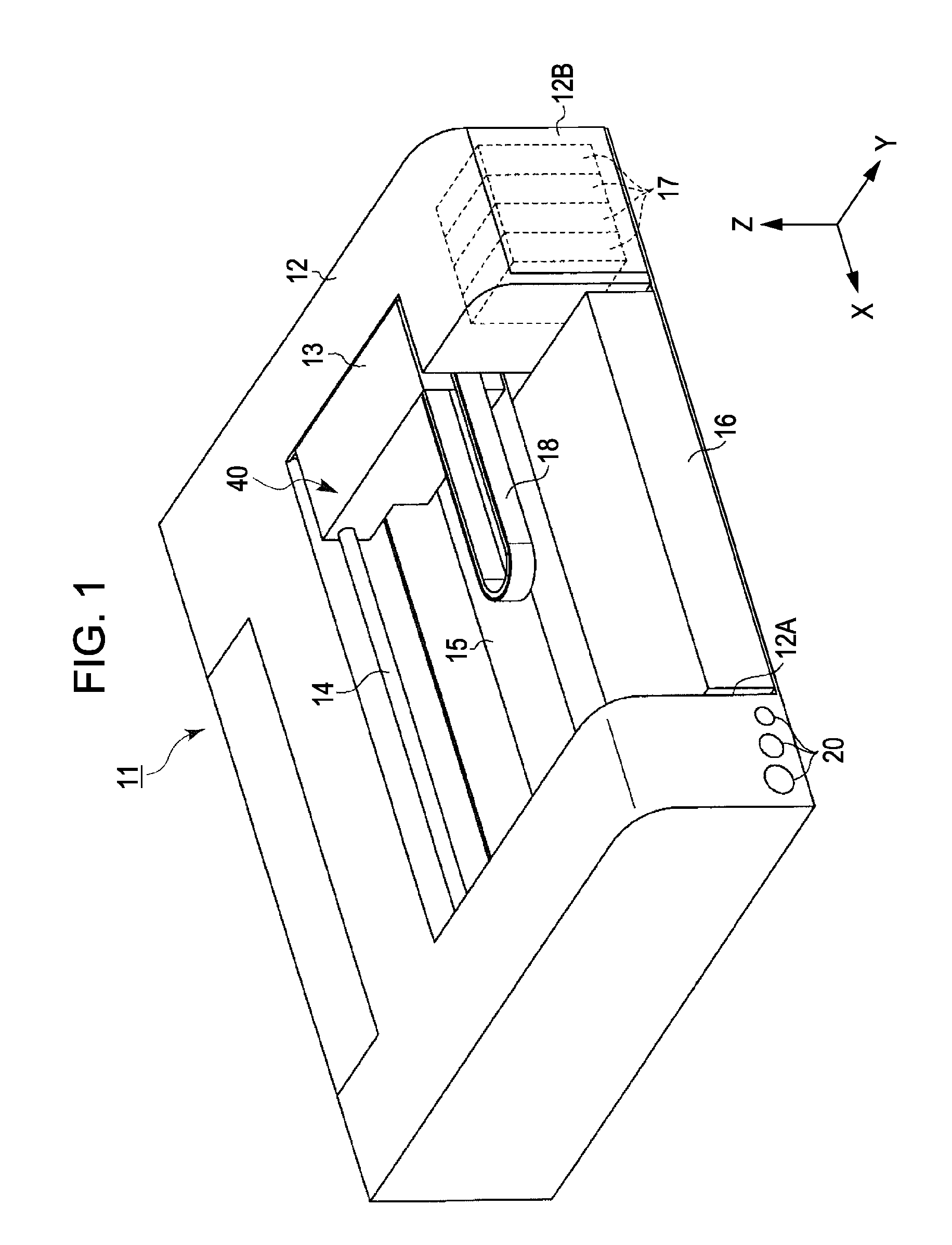
[0031]With reference to the accompanying drawings, exemplary embodiments of the present invention will now be explained in detail. FIG. 1 is a perspective view that schematically illustrates an example of the configuration of a printer, which is an example of an image formation apparatus according to an exemplary embodiment of the invention. As illustrated in FIG. 1, a printer 11 has a box-like body 12, which has the shape of a substantially rectangular parallelepiped. A movable carriage 13 is provided in the center space of the body 12 of the printer 11. A guide main shaft 14 is provided in the center space of the body 12 so as to extend in a main scan direction. The carriage 13 can reciprocate along the guide main shaft 14 in the main scan direction. The main scan direction is shown as the horizontal direction in FIG. 1.

[0032]As illustrated in FIG. 1, a platen 15 is provided in the center area of the body 12 of the printer 11 when viewed in plan. Specifically, the platen 15, which...


PUM


Abstract

A recording apparatus includes: a recording head that performs recording on a recording target medium; a driving mechanism that is capable of causing the recording head to move closer to the recording target medium or move away from the recording target medium; and a controlling section that determines driving amount for one driving operation that is performed by the driving mechanism on the basis of results of a comparison made between a first recording head movement direction that is taken or to be taken in the one driving operation and a second recording head movement direction that was taken in another driving operation that is immediately before the one driving operation and thus precedes the one driving operation.

Description

BACKGROUND[0001]1. Technical Field[0002]The present invention relates to a recording apparatus that is provided with a recording head that performs recording on a recording target medium and is further provided with a driving mechanism that is capable of causing the recording head to move in a direction toward the recording target medium and away from the recording target medium. In the following description of this specification, the term “recording apparatus” according to an aspect of the present invention encompasses various kinds of apparatuses, devices, machines, equipment, and the like such as an ink-jet printer, a wire dot printer, a laser printer, a line printer, a copying machine, and a facsimile machine, though not limited thereto.[0003]2. Related Art[0004]As described in JP-A-2004-314591, a recording apparatus of related art is provided with a carriage, a platen, a guiding unit, a working unit, and a power transmission unit. The platen is an example of a recording target ...

Claims


Application Information

Patent Timeline
Patent Type & Authority Patents(United States)
IPC IPC(8): B41J29/38B41J11/20
CPCB41J25/308
Inventor OKAZAWA, YOSHIYUKINAKAMURA, KAZUHISA
Owner SEIKO EPSON CORP
Why Eureka
Try Eureka