Multi Passage Fuel Manifold and Methods of Construction

a fuel manifold and multi-channel technology, which is applied in the direction of machines/engines, combustion types, lighting and heating apparatus, etc., can solve the problems of increasing the size and weight increasing the complexity of the fuel manifold system construction, and reducing the overall fuel burning efficiency of the engine, so as to minimize the number of seams or joints required

Active Publication Date: 2010-03-04
WOODWARD GOVERNOR CO
View PDF8 Cites 23 Cited by
  • Summary
  • Abstract
  • Description
  • Claims
  • Application Information

AI Technical Summary

Benefits of technology

[0007]Accordingly, in one aspect, the present invention provides a multi zone fuel manifold with any number of separate internal partitions or passages integrally formed together in a single assembly, reducing not only the size of a multi zone fuel manifold of the prior

Problems solved by technology

As will be appreciated, the more complex the fuel system requirements, the more complex the fuel manifold system construction.
For example, where three or more separate fuel conduits are required by the application (to supply additional fuel nozzles, for cooling or for staging

Method used


Image

  • Multi Passage Fuel Manifold and Methods of Construction
  • Multi Passage Fuel Manifold and Methods of Construction
  • Multi Passage Fuel Manifold and Methods of Construction

Examples


Embodiment Construction

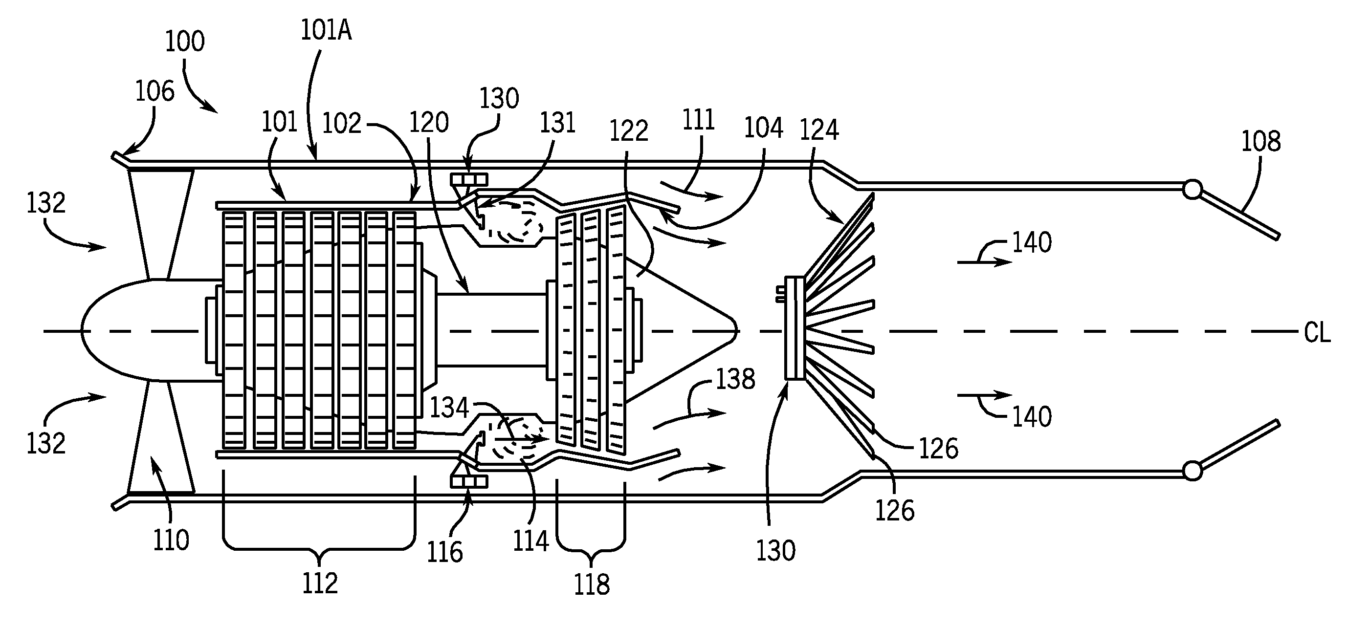
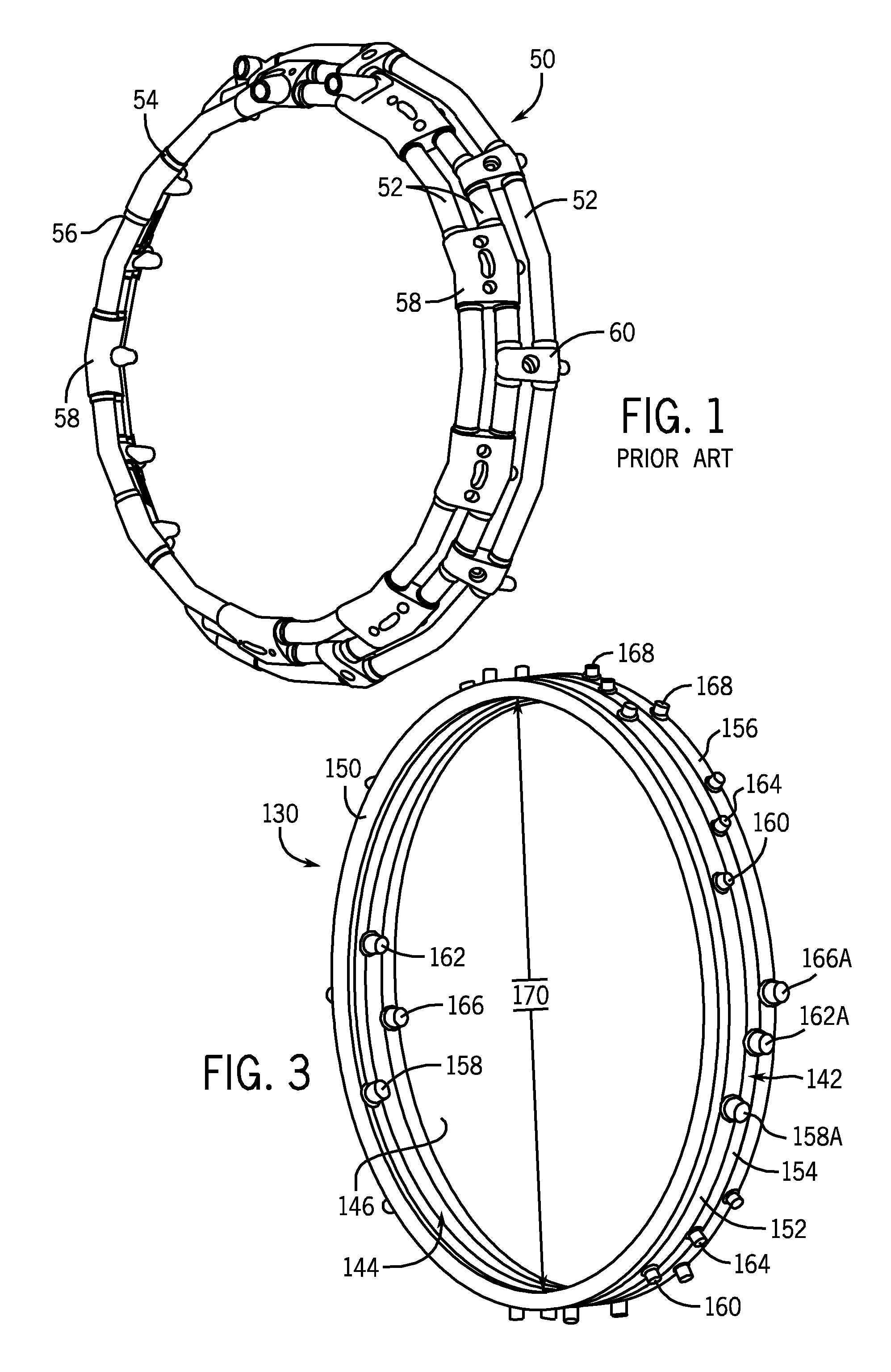
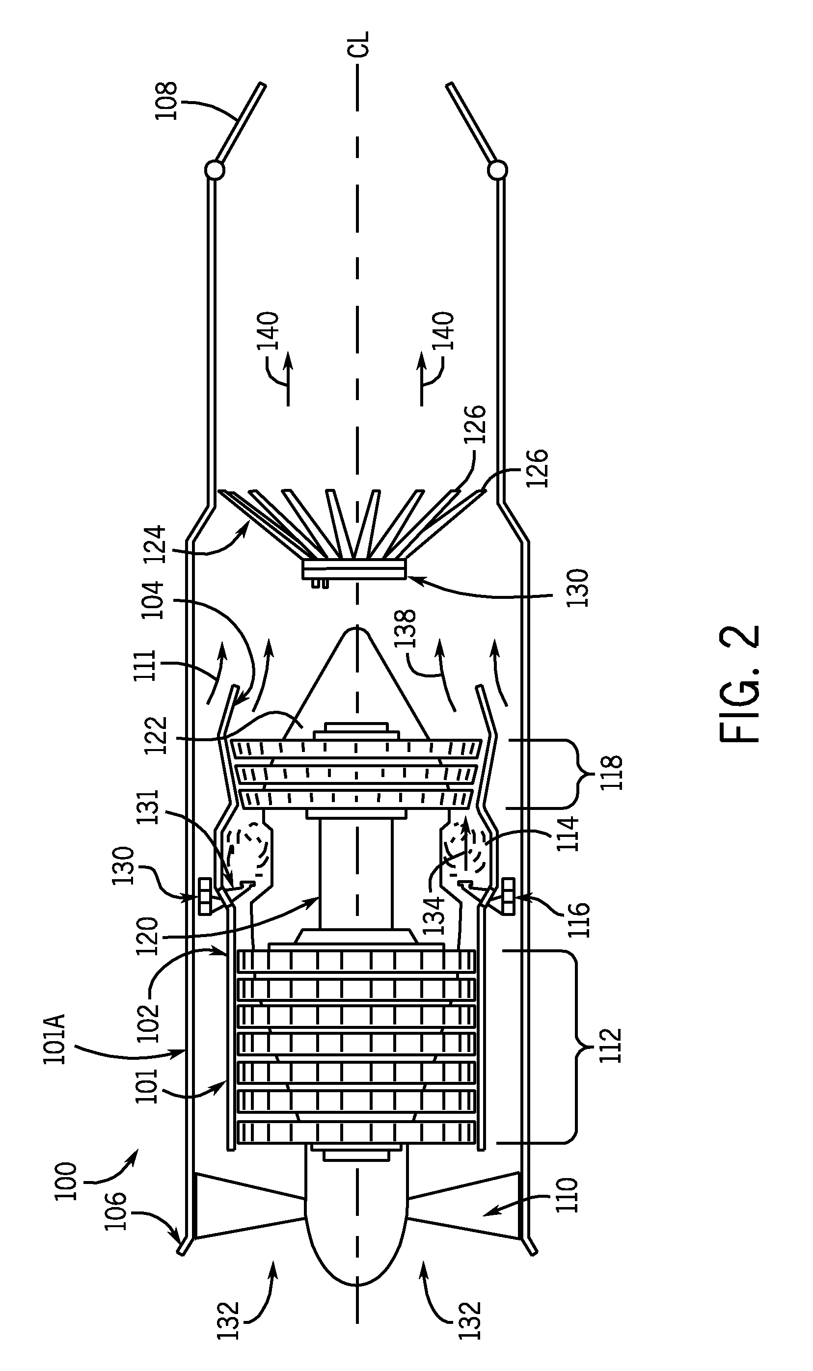
[0023]An integral multi zone fuel manifold 130 constructed in accordance with the teachings of the present invention is shown and described with reference to FIGS. 2 through 8. It will be appreciated that although the fuel manifold 130 is described with respect to use within a gas turbine engine 100, such application is intended as only one example of the type of engine or combustion system that can be utilized with the fuel manifold 130 of the present invention.

[0024]Turning first to FIG. 2, a cross sectional view of the gas turbine engine 100 incorporating the integrally formed, multichannel fuel manifold 130 constructed in accordance with the present invention is shown. In its simplest form, the turbine engine 100 includes a fan casing indicated generally at 101A, an inner engine core housing or casing 101 having an external surface 102, an engine exhaust casing, indicated generally at 104, an upstream or inlet end 106 and a downstream or outlet end 108. From the upstream end 106...


PUM


Abstract

Integrally formed, multi zone fuel manifolds for gas turbine engines and methods of construction are provided. The fuel manifold includes a plurality of annular channel members positioned adjacent each other, aligned and coupled together at the inner and outer peripheral sides thereof, with each pair of channel members defining a separate fluid conduit or passage within the manifold assembly. The fuel manifold can be constructed of any number of stacked and secured channel members to provide a compact multi zone fuel manifold having the desired number of fluid conduits or passages with a minimum number of sealed joints.

Description

FIELD OF THE INVENTION[0001]This invention generally relates to fuel delivery systems for combustion engines and more particularly to multichannel fuel manifolds for gas turbine engines.BACKGROUND OF THE INVENTION[0002]Gas turbine engines, of the type typically used in aircraft applications, include, in serial flow communication, a fan section, through which ambient air is drawn into the engine, a multistage compressor for pressurizing the incoming air, a combustion section, in which the high pressure air is mixed with atomized fuel and ignited, and a turbine section that extracts the energy from hot gas effluent to drive the compressor and fan, producing desired engine thrust. An augmentor is used primarily to provide extra thrust for relatively short periods of time, which may be required during e.g., takeoff and high speed maneuvers, and can also be included to increase the thrust generated by engine. To achieve this, the augmentor injects additional fuel into the exhaust gases e...

Claims


Application Information

Patent Timeline
IPC IPC(8): B05B1/14
CPCF02C7/222F23R3/28F23R3/34F05D2230/237Y02T50/671F05D2230/236F05D2230/232F23R2900/00018Y02T50/60
Inventor HOUTMAN, KENNETH N.LEE, FEI PHILIP
Owner WOODWARD GOVERNOR CO
Why Eureka
Try Eureka