Positioning apparatus

a technology of positioning apparatus and adjusting rod, which is applied in the direction of photomechanical apparatus, instruments, manufacturing tools, etc., can solve the problems of insufficient stiffness, low stiffness of the intermediate stage, and hollow structure of the intermediate stage, and achieve the effect of low stiffness

Inactive Publication Date: 2006-12-26
NSK LTD
View PDF15 Cites 22 Cited by
  • Summary
  • Abstract
  • Description
  • Claims
  • Application Information

AI Technical Summary

Benefits of technology

[0009]In order to solve the drawback, the present invention aims at providing a positioning apparatus which is formed in, e.g., a hollow shape, and has mitigated the previously-described drawback in the stage having low stiffness in a yawing direction, by means of putting contrivance into a layout of guide elements or the like.
[0011]According to the invention, stiffness, in a yawing direction of the stage, of the guide elements provided on the same side where the drive elements are provided is made higher than that of the guide elements provided in an area opposite the area where the drive element is provided. As a result, vibrations of the drive element in the yawing direction of the stage are reliably restrained, thereby improving the yawing stiffness of an area of the stage opposite the area where the drive element is provided. Specifically, a vibratory eigenvalue of the stage in the yawing direction thereof can be increased.
[0013]As will be described later, an examination performed by the present inventor shows that addition of another guide element in the area of the stage opposite the area where the drive element is provided is not effective, but addition of the same in the same area of the stage where the drive element is provided is effective. Addition of another guide element in the area where no drive element is provided is also conceivable. However, in such a case little effect is yielded. When the stage has low stiffness, the vibratory eigenvalue in the yawing direction can be increased by adding the guide element to only the same area of the stage where the drive element is provided.

Problems solved by technology

Since the through holes are formed in the above-described intermediate stages, there arises a problem of the intermediate stages having low stiffness; especially, insufficient stiffness in a yawing direction.
The hollow structure of the intermediate stages has originally suffered a problem of low horizontal stiffness of the entire intermediate stages, because the hollow structure deteriorates the stiffness of the intermediate stages acting as sheet materials.
Therefore, there is a drawback of the stiffness of the intermediate stages in the yawing direction being low.
Hence, there is a problem of the inability to accurately position the stage.

Method used


Image

  • Positioning apparatus
  • Positioning apparatus
  • Positioning apparatus

Examples


Embodiment Construction

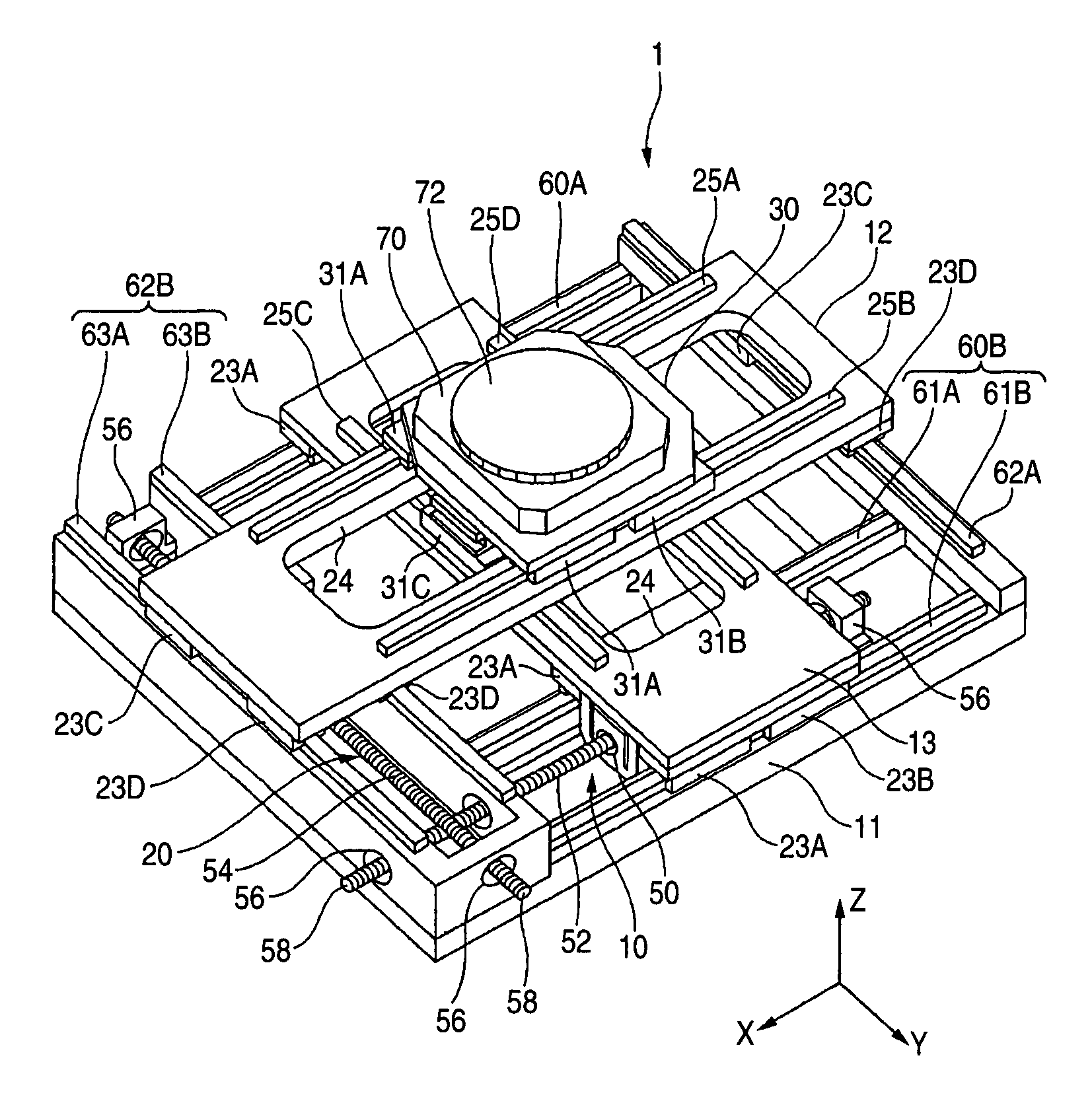
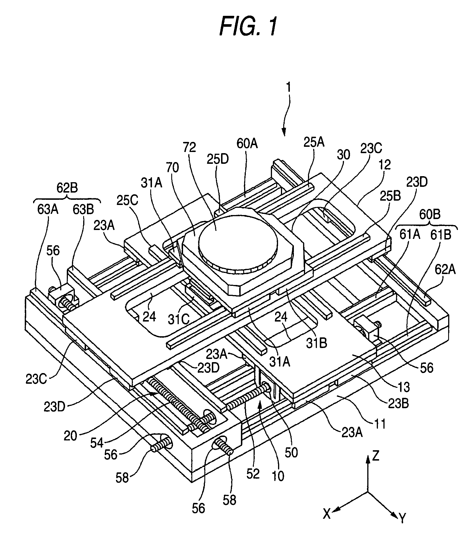
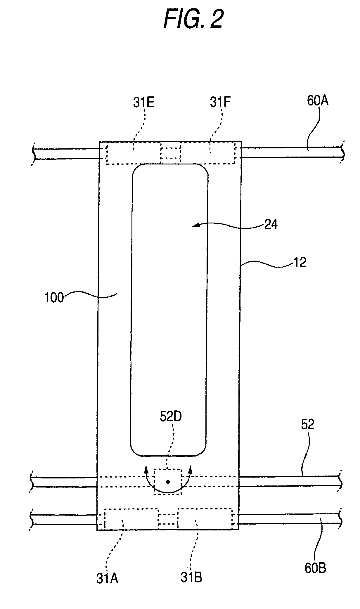
[0023]An embodiment of a positioning apparatus according to the present invention will now be described by reference to FIG. 1. The present embodiment is directed toward the positioning apparatus which is disposed in a vacuum chamber and comprises an X-Y stage capable of positioning an object of positioning in two dimensions. The positioning apparatus is suitable for use with, e.g., ion implantation or a beam exposure system. Those constituent elements which are the same as those described by reference to FIG. 2 are assigned the same reference numerals.

[0024]Reference numeral 1 designates the overall configuration of a positioning apparatus serving as an X-Y stage when viewed from an oblique direction thereof. The positioning apparatus 1 comprises a base 11; a first positioning mechanism 10 which is provided on the base 11 and positions a first slider 13 (an intermediate stage) in an X-axis direction (a first direction); a second positioning mechanism 20 which is placed on the base ...


PUM

PropertyMeasurementUnit
stiffness ratioaaaaaaaaaa

Abstract

A positioning apparatus has a stage, guide elements provided on both ends of the stage, and drive elements which are provided at one of both ends of the stage and move the stage along the guide elements. Like linear guide rails 61A, 61B and linear guide bearings 23A, 23B, two guide elements are provided in an area where a ball screw shaft 52 serving as a drive element is placed. One guide element is provided in an area where a non-drive element is provided.

Description

BACKGROUND OF THE INVENTION[0001]The present invention relates to a positioning apparatus for use with a semiconductor exposure system to be used for forming a pattern on a flat substrate, such as a semiconductor wafer or a liquid-crystal panel, as well as with an assembly / inspection apparatus and a precision machine tool.[Patent Document 1] JP-A-2002-158274[0002]A positioning apparatus described in, e.g., JP-A-2002-158274, is the positioning apparatus of this type. This patent publication discloses a positioning apparatus intended for providing a high-precision, long-life positioning apparatus which can actuate a slider at high speed and has achieved space saving. The positioning apparatus has a first positioning device for positioning a first slider (an intermediate stage) to a base in an X-axis direction by means of a first drive device; and a second positioning device for positioning a second slider (the intermediate stage) on the base in a Y-axis direction by means of a second ...

Claims


Application Information

Patent Timeline
Patent Type & Authority Patents(United States)
IPC IPC(8): G01D21/00B23Q1/00G03F7/20H01L21/027H01L21/68
CPCG03F7/70058G03F7/70716H01L21/682
Inventor NAKAMURA, TSUYOSHISAJI, NOBUHITOSUGITA, YOSHIFUMITANIGUCHI, MASATO
Owner NSK LTD
Why Eureka
Try Eureka