Flexible biomonitor with EMI shielding and module expansion

a biomonitor and module technology, applied in medical science, diagnostics, printed circuits, etc., can solve the problems of inability to properly protect electronic devices, inability to reduce the area of physiological plasters, and wear comfort, so as to reduce the probability of nosocomial infection, reduce the occupied area, and wear comfort

Active Publication Date: 2012-10-16
IND TECH RES INST
View PDF13 Cites 13 Cited by
  • Summary
  • Abstract
  • Description
  • Claims
  • Application Information

AI Technical Summary

Benefits of technology

[0009]Another object of the present invention is to provide a flexible biomonitor, in which a plurality of through holes for conducting electricity are formed on the two-sided flexible main circuit board enabling the electronic device and the sensor to be mounted respectively on the two sides of the two-sided flexible main circuit board for reducing occupied area and providing comfortable wear.
[0010]A further object of the present invention is to provide a flexible biomonitor capable of transmitting a hybrid signals monitored thereby wirelessly using RFID technology. Accordingly, the purpose of home care is achieved by use of the network system of the medical center to perform the personalized remote real-time monitoring and to reduce the probability of having nosocomial infection by reducing the number of hospital visits of patients, aged persons, and children. Thereupon the medical quality is improved.

Problems solved by technology

In other words, the sensor and the electronic device are mounted on the same side of the physiological plaster, which will cause the plaster to have the following drawbacks: (1) the area of the physiological plaster cannot be reduced; (2) the wear is less comfortable because of perspired sweat from the body; (3) the electronic device cannot be properly protected; and (4) EMI shielding is not available so that the signal transmitted from the physiological plaster may be easily interfered.
This requires complicated manufacturing processing.

Method used


Image

  • Flexible biomonitor with EMI shielding and module expansion
  • Flexible biomonitor with EMI shielding and module expansion
  • Flexible biomonitor with EMI shielding and module expansion

Examples


Embodiment Construction

[0027]The above-mentioned features and advantages of this invention, and the manner of attaining them, will become more apparent and the invention will be better understood by reference to the following description of embodiments of the invention taken in conjunction with the drawings. But, the scope of the present invention is not limited to the drawings.

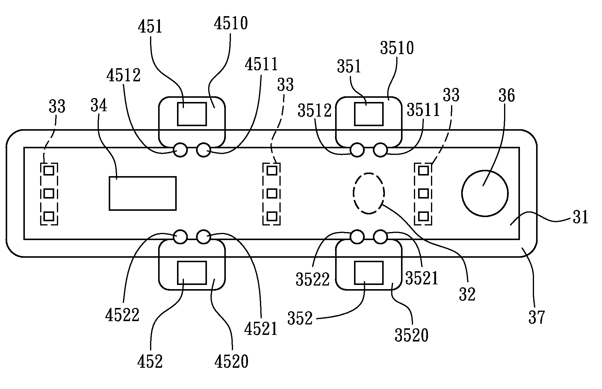
[0028]Referring to FIG. 3A and FIG. 4, a top view and a functional diagram of a flexible biomonitor of one embodiment of the present invention are shown, respectively. The flexible biomonitor comprises a flexible substrate 31, a hybrid sensor 32, a plurality of IC devices 33, a central processing module 34, a RF transmitter circuit 351, an antenna 352, a power supply 36, and a package 37.

[0029]The flexible substrate 31 has a circuit apparatus formed on the flexible substrate 31. The circuit apparatus has a circuit layout (not shown) mounted thereon. More particularly, the circuit apparatus comprises: a bottom circuit layer, connect...


PUM


Abstract

A flexible biomonitor comprises: a flexible substrate having a circuit apparatus, a hybrid sensor, a plurality of IC devices, a central processing module, a RF transmitter circuit, an antenna, and a power supply. Thereupon the flexible biomonitor can be plastered on the skin where the human body needs to be monitored to achieve the purposes of reducing occupied area, providing comfortable wear and achieve compactness, module expansion and EMI shielding. Besides, it is capable of remote real-time monitoring this signal to achieve the purpose of home care.

Description

CROSS REFERENCE TO RELATED PATENT APPLICATION[0001]This is a continuation in part application of an application Ser. No. 11 / 132,216 filed on May 19, 2005, which further claims the benefit of Taiwan application Serial No. 94108277, filed Mar. 21, 2005; the subject matter of which is incorporated herein by reference.FIELD OF THE INVENTION[0002]The present invention relates to a flexible biomonitor with EMI shielding and module expansion, and more particularly to a flexible biomonitor using at least a pair of flexible wing circuit boards having radio frequency (RF) components being disposed thereon separated from a two-sided flexible main circuit board while being discretely coupled to the two-sided flexible main circuit board through a pair of pads attached to the two-sided flexible main circuit board so as to achieve compactness, module expansion and EMI shielding.BACKGROUND OF THE INVENTION[0003]According to statistic data of Frost and Sullivan business consulting firm in Year 2000,...

Claims


Application Information

Patent Timeline
Patent Type & Authority Patents(United States)
IPC IPC(8): A61B5/00
CPCA61B5/0002A61B5/01A61B5/02438A61B2560/0412A61B2562/182H05K1/189
Inventor HU, YING-CHIANGKE, TING-CHENCHANG, WEN-YINGCHU, CHUN-HSUN
Owner IND TECH RES INST
Why Eureka
Try Eureka