Method for displaying a thermal image in an IR camera and an IR camera

a thermal image and camera technology, applied in radiation thermography, optical radiation measurement, instruments, etc., can solve the problems of operator completely missing a thermal anomaly, difficulty in interpreting and identifying the location of objects shown difficulty in detecting thermal anomalies in the infrared image, so as to increase the accuracy of temperature measurements

Active Publication Date: 2012-10-16
FLIR SYST AB
View PDF21 Cites 25 Cited by
  • Summary
  • Abstract
  • Description
  • Claims
  • Application Information

AI Technical Summary

Benefits of technology

[0013]An advantage of the above described invention is that it allows you to determine immediately, on-site, if a building is well insulated or not. It presents an easily interpreted and understandable thermal image which instantly draws a users attention to an identified critical area.
[0016]This feature advantageously provides the user with an opportunity to determine whether or not, for example, a wall fulfils the thermal transmission properties guaranteed by a contractor or a supplier.
[0020]This feature further increases the accuracy of the temperature measurements.

Problems solved by technology

This leads to difficulties in interpreting and identifying the location of objects shown in the infrared image.
The difficulties and uncertainties in interpreting the infrared images also slow down the inspections since the operator often has to look closer and from different angles to be really sure that he has identified the right target, in which the thermal anomaly is actually found.
Further, it can also lead to an operator completely missing a thermal anomaly since the thermal anomaly is not clearly defined and could be hard to recognize just by looking at the thermal image.

Method used


Image

  • Method for displaying a thermal image in an IR camera and an IR camera
  • Method for displaying a thermal image in an IR camera and an IR camera
  • Method for displaying a thermal image in an IR camera and an IR camera

Examples


second embodiment

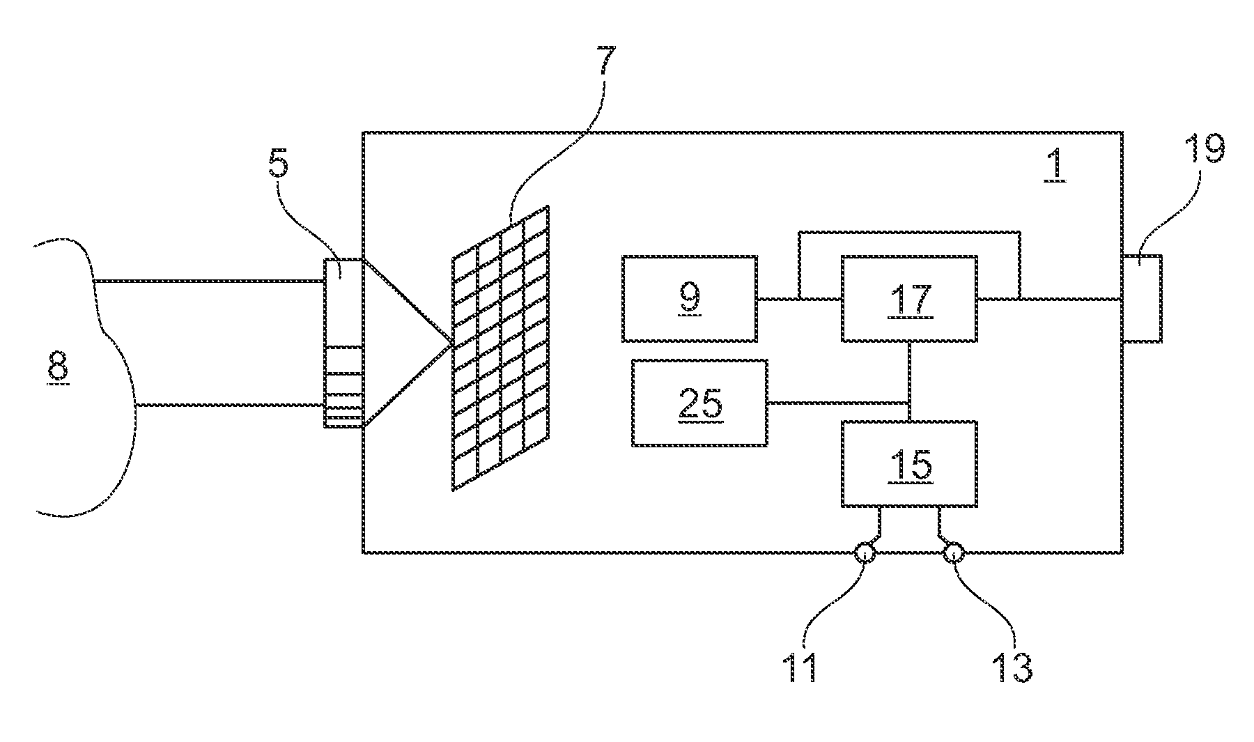
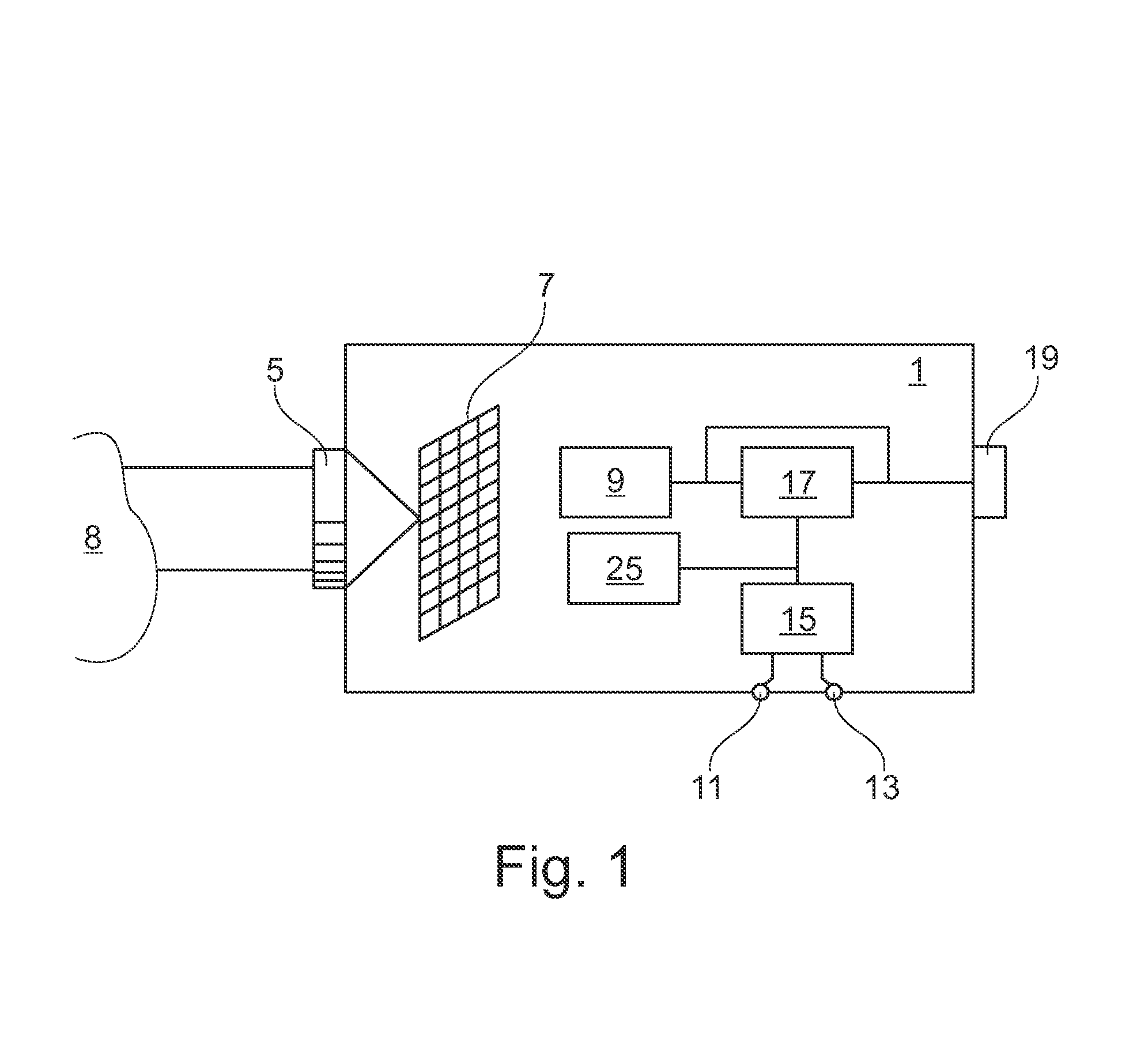
[0054]The second additional feature, shown in FIG. 3 in which the reference numerals refers to the same objects as in FIG. 1, is for the IR camera to include distance input means 27, for example, a laser measuring device, arranged to register and store the distance between the captured object 8 and the IR camera 1, which also could be compensated for when displaying the captured thermal image 10 according to the temperature color alarm. Alternatively, information about the distance between the captured object 8 and the IR camera 1 may be measured separately and input to the camera in another way, e.g. manually.

[0055]The measured distance can also be stored in the storage means 25 in the IR camera 1, as shown in FIG. 1, or outside the camera in ways common in the art.

[0056]This second additional feature can of course be implemented in an IR camera also including the previously mentioned feature in order to achieve as accurate measurements as possible.

[0057]Alternatively, as depicted...

fourth embodiment

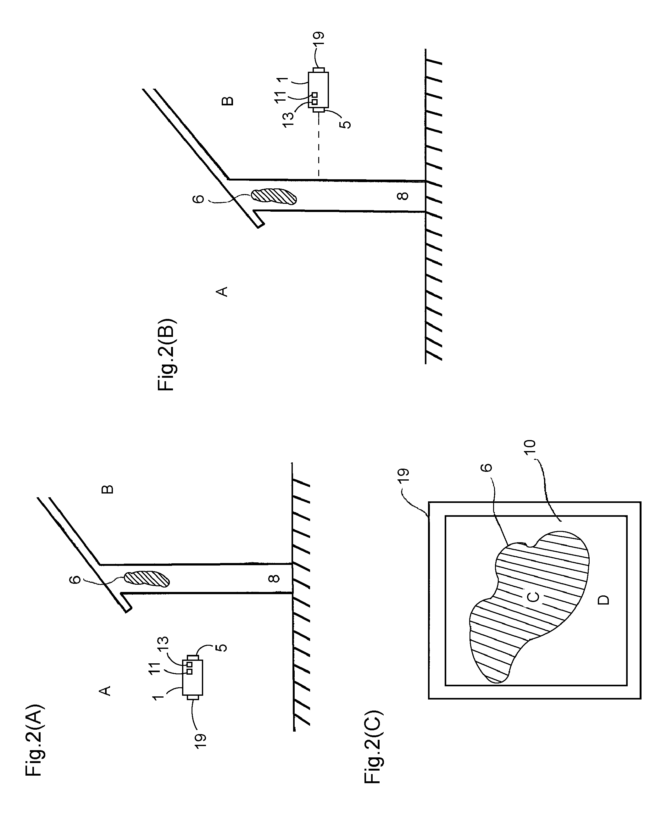
[0058] the IR camera 1 could comprise calculating means further arranged to calculate thermal transmission coefficients using the indoor and outdoor temperature measurements, as described in connection to FIG. 2(A), 2(B) and 2(C), together with thermal images.

[0059]However, this requires that the user inputs additional information manually, for example, information regarding the construction of the wall, what kind of building materials, etc. For example, a static one-dimensional thermal transmission coefficient Q can be calculated using the indoor and outdoor temperature measurements (TA, TB) according to the following formula:

[0060]Q=λd⁢(TA-TB)

where λ is an approximation of the thermal conductivity of a wall and d is the thickness of the wall, both of which have to be manually registered in the IR camera. This simple and general example illustrates how wall properties can be calculated using the present invention, but should not be considered limited towards more complex calculatio...


PUM

PropertyMeasurementUnit
thermalaaaaaaaaaa
thermal transmissionaaaaaaaaaa
temperatureaaaaaaaaaa

Abstract

The invention is achieved by using a method for displaying a thermal image in an infrared (IR) thermal camera, comprising the steps of registering an outdoor temperature value, registering an indoor temperature value, calculating an isotherm level by using the registered temperature values and a temperature color alarm level, imaging a surface area to create an image of the temperature distribution in at least a part of the surface area, comparing the surface area temperature in at least one image point of the thermal image to the isotherm level, adjusting the color of the at least one image point in dependence of the relation between the surface area temperature in said at least one image point and the isotherm level and displaying the colored thermal image.The invention allows you to determine immediately, on-site, if a building is well insulated or not. It presents an easily interpreted and understandable thermal image which instantly draws a users attention to an identified critical area.

Description

TECHNICAL FIELD[0001]The present invention relates to a method for displaying a surface area temperature using indoor and outdoor temperature measurements in an infrared (IR) thermal camera, and in particular for displaying critical areas when monitoring and inspecting the condition of buildings.BACKGROUND OF THE INVENTION[0002]IR cameras can be used in a number of different situations, for example, when inspecting buildings or walls looking for areas with missing or bad insulation, structural damages, for example missing reinforcements, cracks in concrete walls, moisture, or water damages.[0003]An infrared (IR) camera is used for capturing, displaying and storing thermal images. In addition to the thermal data of the captured objects other types of information, for example text and / or voice comments, visual images and environmental data, can also be digitally attached to the thermal image.[0004]It is of great interest not only to view the thermal images but also to be able to tell ...

Claims


Application Information

Patent Timeline
Patent Type & Authority Patents(United States)
IPC IPC(8): H04N9/43H01L25/00G02F1/01
CPCG01J5/10G01J2005/0077G01J2005/0081G01J5/48
Inventor HAMRELIUS, TORBJORNAHLSTROM, MATS
Owner FLIR SYST AB
Why Eureka
Try Eureka