Stabilized step hull utilizing a ventilated tunnel

a ventilated tunnel and step hull technology, applied in the direction of special-purpose vessels, vessel construction, transportation and packaging, etc., can solve the problems of increased speed, increased area and its accompanying excessive drag, and compromised directional stability, so as to improve directional stability and control, reduce the amount of drag, and simplify the construction

Active Publication Date: 2012-10-23
PETERS MICHAEL PAUL
View PDF6 Cites 18 Cited by
  • Summary
  • Abstract
  • Description
  • Claims
  • Application Information

AI Technical Summary

Benefits of technology

[0014]In view of the limitations presented in the background herein, the present invention provides a novel design, which maintains, and more likely reduces, the amount of drag, whil

Problems solved by technology

Powerboats utilize planing to reduce displacement and the resulting friction/wave resistance resulting in an increase in speed.
The conflict is that, in order to have the area needed for displacement operation, e

Method used


Image

  • Stabilized step hull utilizing a ventilated tunnel
  • Stabilized step hull utilizing a ventilated tunnel
  • Stabilized step hull utilizing a ventilated tunnel

Examples


Embodiment Construction

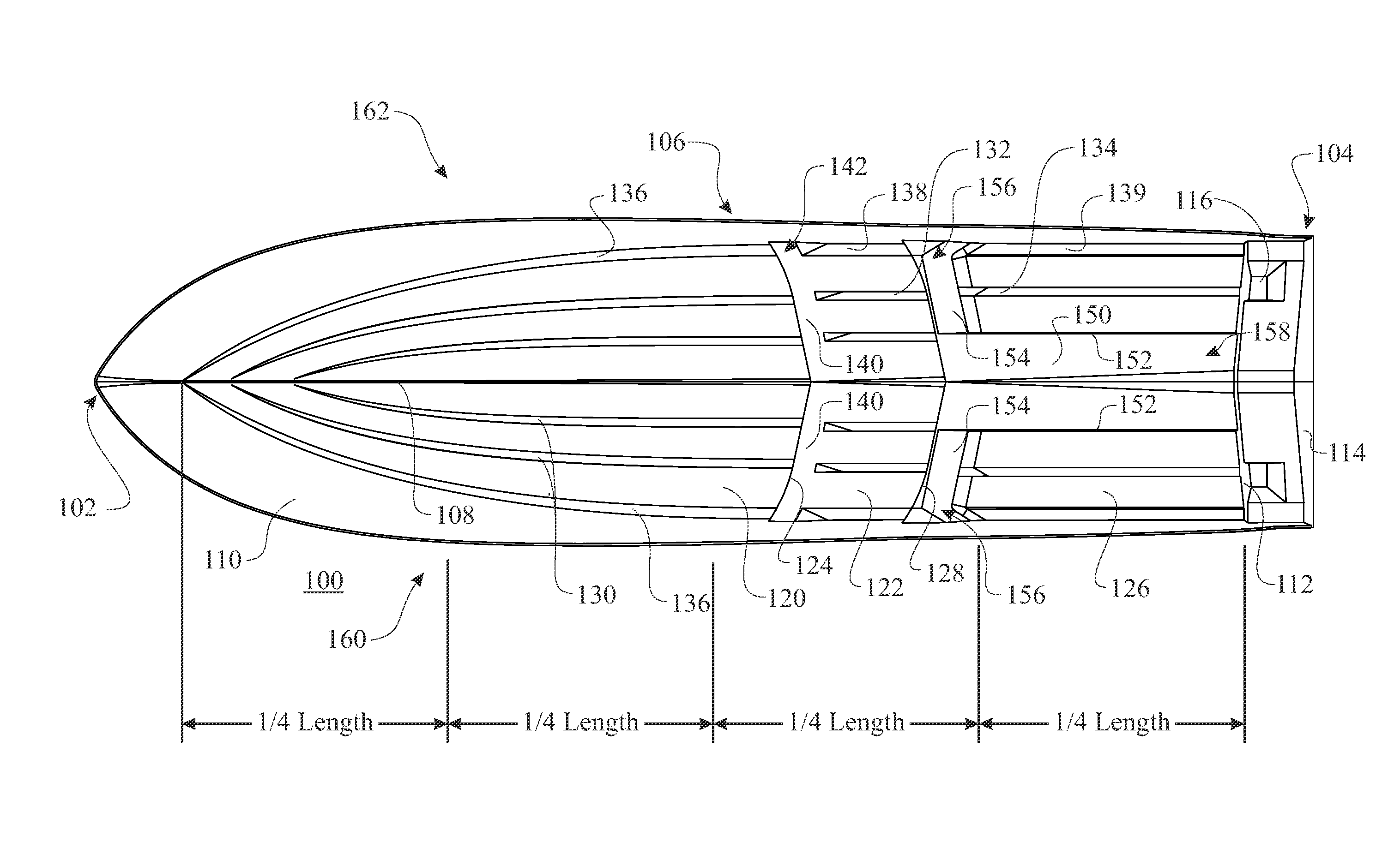
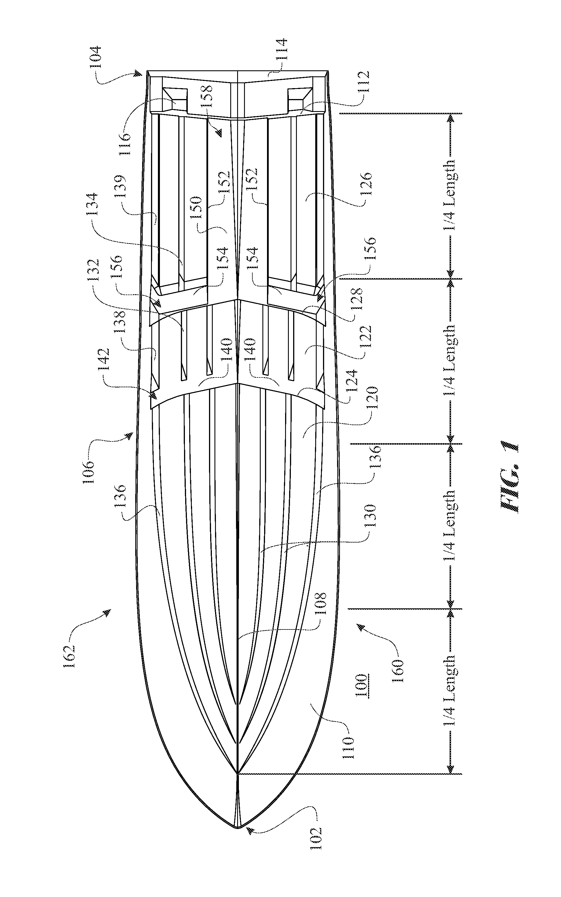
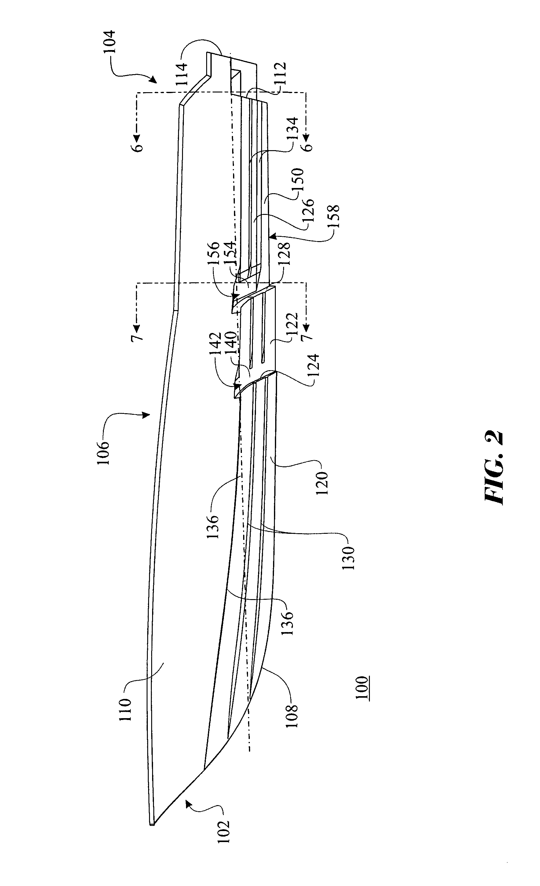
[0040]Referring initially to FIGS. 1 through 8, a high speed power boat hull is shown generally as reference numeral 100. A bottom view of the hull 100 is shown in FIG. 1, the illustration presenting an exemplary embodiment of the present invention. An elevation view of the hull 100 is shown in FIG. 2, with a magnified view of the aft section presented in FIG. 3. An isometric view of the bottom of the hull 100 is presented in FIG. 4, with a magnified view of the aft section presented in FIG. 5. A rear view of the hull 100 taken just aft of a transom 112 taken along section 6-6 of FIG. 2 is illustrated in FIG. 6. A sectional view of the hull 100 taken just aft of the leading edge of a ventilated tunnel 150 taken along section 7-7 of FIG. 2 is illustrated in FIG. 7. A rear view of the hull 100 as viewed front behind a motor mount 114 is best shown in FIG. 8.

[0041]The exemplary embodiment presents a powerboat hull 100 defined by three primary sections, a bow 102, a stern 104 and a mids...


PUM


Abstract

A high speed powerboat hull (100) incorporating a tunnel ventilation channel (154) spanning between a starboard (160) and port (162) side of the hull (100). The hull (100) has a “V” shaped forward section. The ventilated tunnel (150) is provided as a recess having two substantially vertical sidewalls (152) arranged parallel to each other located along each of the two outer edges of the tunnel (150). The tunnel (150) is disposed longitudinally between the ventilated channel (154) and a transom (112). The ventilated tunnel (150) is in fluid communication with the ventilation channel (154). The hull (100) can further comprise at least one stepped hull section (122, 126).

Description

CROSS-REFERENCE TO RELATED APPLICATIONS[0001]This application claims the benefit of U.S. provisional patent application Ser. No. 60 / 904,811 filed on Mar. 5, 2007, by the same inventor.BACKGROUND OF THE INVENTION[0002]1. Field of the Invention[0003]The invention relates generally to an improved planing hull design for a power boat and, more specifically, to a high speed power boat having an improved hull design shape including a tunnel section that is positioned center and aft of an at least one transverse step.[0004]2. Discussion of the Related Art[0005]High speed powerboats utilize various design features for speed and stability. Powerboats utilize planing to reduce displacement and the resulting friction / wave resistance resulting in an increase in speed. Offshore powerboats require additional features to ensure stability while running at high speeds over a rough water surface.[0006]Planing refers to the hydrodynamic process whereas, on increasing speed, the boat is lifted up relat...

Claims


Application Information

Patent Timeline
IPC IPC(8): B63B1/38
CPCB63B1/042B63B1/32B63B1/38Y02T70/122Y02T70/10
Inventor PETERS, MICHAEL PAUL
Owner PETERS MICHAEL PAUL
Why Eureka
Try Eureka