Solid state light source light bulb

a light source and solid state technology, applied in the direction of discharge tube luminescnet screens, semiconductor devices for light sources, lighting and heating apparatus, etc., can solve the problems of reducing the reducing the efficiency of current state of the art led technology, and reducing overall light emission and bulb durability. , to achieve the effect of prolonging the life and durability of the bulb, discharging more heat from the light source into the environmen

Inactive Publication Date: 2012-10-23
RENESSELAER POLYTECHNIC INST
View PDF15 Cites 87 Cited by
  • Summary
  • Abstract
  • Description
  • Claims
  • Application Information

AI Technical Summary

Benefits of technology

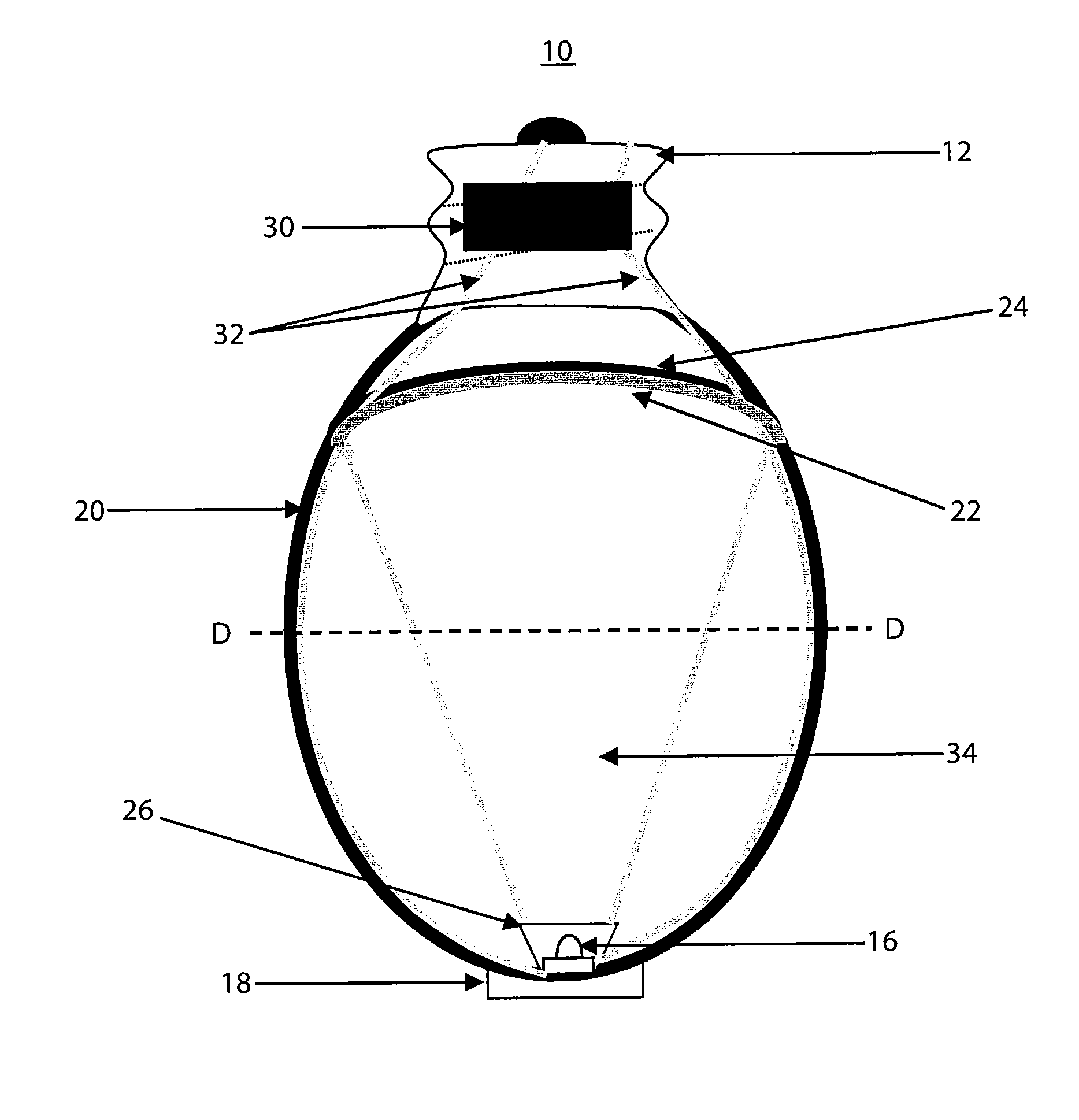
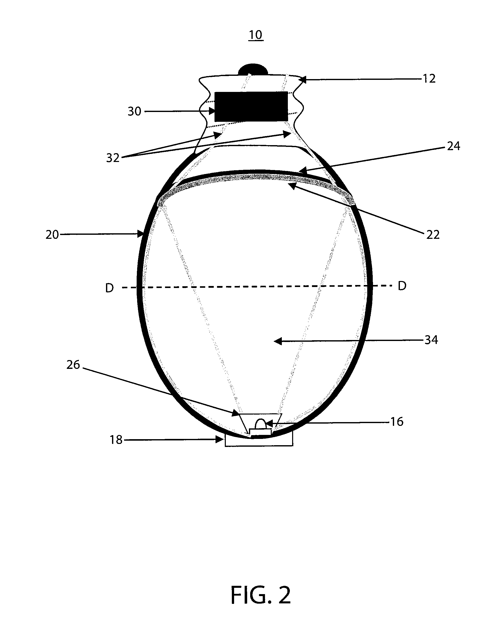
[0010]In another embodiment, the present invention further includes a down conversion material for receiving and down converting at least some of the light emitted by the light source and back transferring a portion of the received and down converted light. The down conversion material is disposed within the bulb envelope, remote from the light source and between the light source and the lamp base. One or more wavelength-converting materials are used to absorb radiation in one spectral region and emit radiation in another spectral region, and the wavelength-converting material can be either a down-converting or an up-converting material. Multiple wavelength-converting materials are capable of converting the wavelength emitted from the light source to the same or different spectral regions. In some embodiments of the present invention, for example those employing a white LED as the light source, a down conversion material may not be necessary as the emitted light is already substantially similar to that produced by an incandescent lamp.
[0014]The embodiments of the present invention place the light source and heat sink at the apex of the light bulb envelope, distant from the lamp base, in order to dissipate more of the heat produced by the light source into the environment. This arrangement enables a greater amount of light to be produced, compared to commercially available SSL-based replacement light bulbs which place the light source and, optionally, heat sink at the lamp base. The configurations of the present invention also aid to ensure that temperatures of the bulb components are maintained, thereby prolonging bulb durability and life span.

Problems solved by technology

Due to their long operation (burn) time and low power consumption, solid state light emitting devices frequently provide a functional cost benefit, even when their initial cost is greater than that of conventional lamps.
Even with these improvements, the current state of the art LED technology is inefficient in the visible spectra.
However, designs incorporating a larger LED or multiple LEDs have been found to present their own challenges.
Recent studies have determined that the heat generated from LEDs decreases overall light emission and bulb durability.
More particularly, the LED device becomes less efficient when heated to a temperature greater than 100° C., resulting in a declining return in the visible spectra.
Extended exposure to high heat also reduces the effective life of the LEDs.
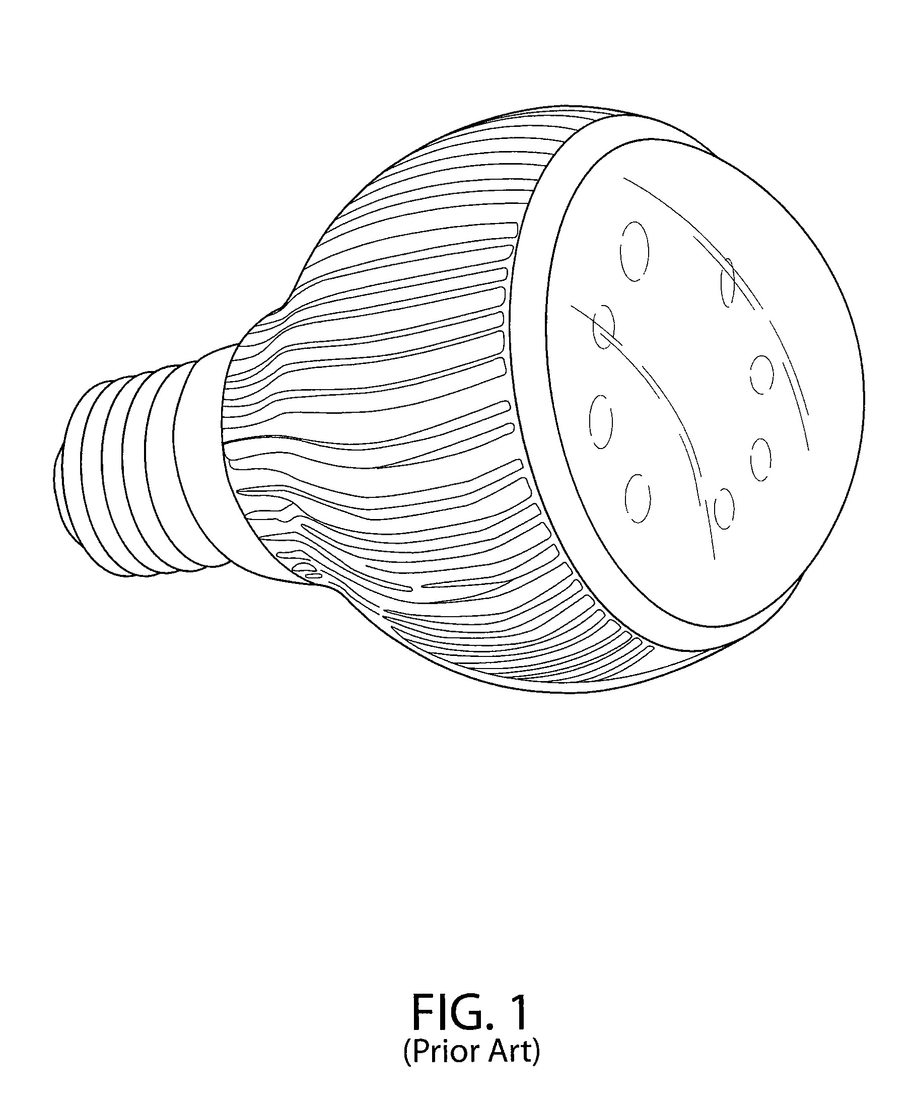
Even though solid state light emitting devices have been advancing rapidly and have exceeded the luminous efficacy of traditional A-lamp incandescent bulbs, there are no SSL-based replacement light bulbs that can produce light levels similar to incandescent lamps, have very high luminous efficacy values, and much longer life time.

Method used


Image

  • Solid state light source light bulb
  • Solid state light source light bulb
  • Solid state light source light bulb

Examples


examples

[0062]In at least one embodiment of the present invention, an LED package with scattered photon extraction (SPE) is implemented. Unlike a typical conventional white LED package, where the down conversion phosphor is spread around the light source or die, in the SPE package of the invention the phosphor layer is moved away from the die, leaving a transparent medium between the die and the phosphor. An efficient geometrical shape for such packages may be determined via ray tracing analysis. It is worth noting that the SPE package requires a different phosphor density to create white light with chromaticity coordinates similar to the conventional white LED package. This difference is a result of the SPE package mixing transmitted and back-reflected light with dissimilar spectra, whereas the conventional package uses predominantly the transmitted light.

[0063]A ray tracing analysis to assess the feasibility of the light guide concept was performed. Additionally, a laboratory evaluation w...


PUM


Abstract

A light emitting apparatus includes a lamp base, a light-transmissive bulb envelope, a light source for emitting light, and a heat sink coupled to the light source. A solid state LED light bulb may further include a down conversion material. The down conversion material is disposed within the bulb envelope, remote from the light source and between the light source and the lamp base. The heat sink may include at least one metal fin and, additionally or alternatively, include a mesh disposed over at least an outer portion of the bulb envelope. A solid state light bulb may include a light guide for directing the light emitted by the light source. The solid state light bulb configurations place the light source and heat sink at the apex of the light bulb envelope, distant from the lamp base, in order to dissipate heat produced by the light source into the environment. In addition, at least part of the heat sink is outside the light bulb envelope to maximize the heat dissipation.

Description

CROSS-REFERENCE TO RELATED APPLICATIONS[0001]This application is a U.S. National Phase Application of PCT International Application No. PCT / US2010 / 037965 filed Jun. 9, 2010 which claimed the benefit of the filing date of U.S. provisional patent application Ser. No. 61 / 268,230, filed Jun. 10, 2009, the disclosure of which is incorporated herein by reference.FIELD OF THE INVENTION[0002]The present invention relates generally to solid-state lighting. Specifically, the present invention relates to a light bulb using solid-state light (SSL) sources, remote phosphor, and a heat sink.BACKGROUND OF THE INVENTION[0003]Solid state light (SSL) emitting devices, including solid state lamps having light emitting diodes (LEDs) are extremely useful, because they potentially offer lower fabrication costs and long term durability benefits over conventional incandescent and fluorescent lamps. Due to their long operation (burn) time and low power consumption, solid state light emitting devices frequen...

Claims


Application Information

Patent Timeline
Patent Type & Authority Patents(United States)
IPC IPC(8): F21V7/00F21V9/40
CPCF21K9/135F21K9/56F21V9/16F21K9/52F21V7/0008F21Y2101/02F21V3/00F21V29/74F21V7/0025F21V29/70F21V13/14F21V23/002F21K9/232F21K9/61F21K9/64F21K9/66F21Y2115/10F21V9/32F21V9/45F21V9/30
Inventor NARENDRAN, NADARAJAHFREYSSINIER, JEAN PAULZHU, YITING
Owner RENESSELAER POLYTECHNIC INST
Why Eureka
Try Eureka