Bonding material, bonded portion and circuit board

a technology of bonded portion and circuit board, which is applied in the direction of manufacturing tools, soddering apparatus, transportation and packaging, etc., can solve the problems of increasing the severity of the regulation of the treatment of industrial waste such as electronic circuit board, and damage to electronic components, and achieves high reliability, low melting point, and high tolerance to stress. high

Active Publication Date: 2012-10-23
PANASONIC CORP
View PDF31 Cites 4 Cited by
  • Summary
  • Abstract
  • Description
  • Claims
  • Application Information

AI Technical Summary

Benefits of technology

[0052]The first invention relating to the present solder material can show a low melting point of 120 degree C. or less by adopting a solder material having a basic composition consisting of Sn, Bi and In. Further, the present solder material can show a significant elongation in a range of at least 80% or more, preferably 85% or more, more preferably 90% or more, particularly preferably 95% or more. Using the present solder material, the bonding temperature, i.e. the mounting temperature substantially equals to 120 degree C. or less may be achieved. In addition, after cured, the solder material may form a bonded portion, which portion has high reliability and high tolerance to stress.
[0053]The second invention relating to the present solder paste can achieve the bonding temperature, i.e. the mounting temperature of 120 degree C. or less, since it comprises a flux component in addition to the solder material of the first invention. After cured, the solder paste forms a bonded portion having high reliability and high tolerance to stress, since the cured solder material shows a significant elongation.
[0054]The third invention relating to the present conductive adhesive can achieve the bonding temperature of 120 degree C. or less and the curing temperature, i.e. the mounting temperature of 120 degree C. or less, since it comprises a suitable resin component in addition to the solder material of the first invention. After cured, the conductive adhesive forms a bonded portion having high reliability and high tolerance to stress, since the cured solder material shows a significant elongation.
[0055]Since the solder material cures after it is sufficiently molten or fused in the heating step, it can produce a conductive path made of an ingot of the metal of the solder material substantially having no break. Accordingly, the bonded portion made of the present solder material, including the solder paste and the conductive adhesive, can achieve stable and low volume resistivity as the bulk metal.
[0056]The present conductive adhesive can effectively prevents insufficient melting of the metal due to the oxidation of the metal, which has a low melting point, in the heating and curing step by adding a resin having reducing property or a curing agent (the second resin component) to the conductive adhesive. Further, the present conductive adhesive can be used at a relatively low mounting temperature, since the alloy having a low melting point can be sufficiently molten at its own melting point.EXPLANATION OF THE DRAWINGS
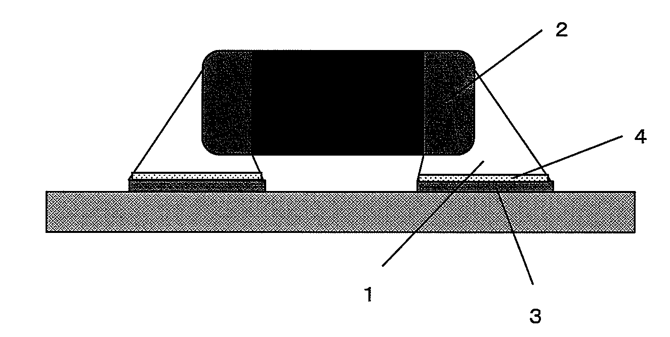
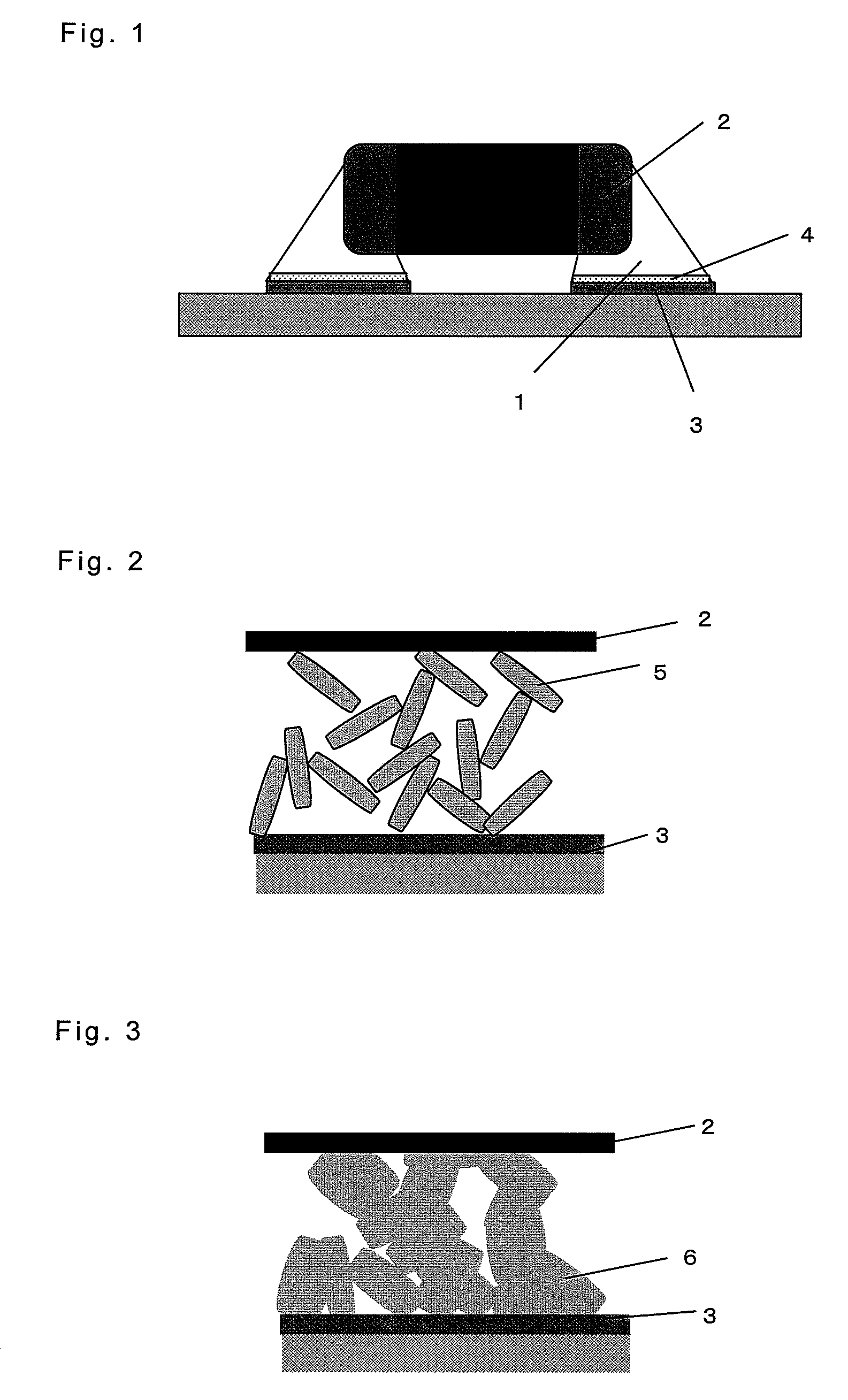
[0057]FIG. 1 shows a schematic view of a conventional bonding structure of an electronic component having electrodes.

Problems solved by technology

While global environmental protection has become of major interest, regulation of treatment of industrial waste such as electronic circuit boards is becoming more severe and lead is becoming a global regulation subject.
n this case, there arises a problem that electronic components may be damaged.

Method used


Image

  • Bonding material, bonded portion and circuit board
  • Bonding material, bonded portion and circuit board
  • Bonding material, bonded portion and circuit board

Examples


second embodiment

(Second Embodiment)

[0080]In a second embodiment of the present invention, each conductive adhesive using each solder material of Examples 1-20 and Comparative Examples 1-6 in the above first embodiment is prepared. As Comparative Example 7, a conductive adhesive containing merely Ag as its metallic component is prepared.

[0081]In each of Examples and Comparative Examples, a thermocurable epoxy resin is used as the resin component. In these Examples, any of Epicoat 828 and Epicoat 807 (manufactured by Japan Epoxy Resin (JER) Co., Ltd.) was used as a preferable Example of the epoxy resin and 2PHZ (manufactured by SHIKOKU CHEMICALS CORPORATION) was used as a hardening agent. In the solder material, commercially available metallic micro fine powder having flake form or powder form may be used. In each Example, the solder paste prepared in the first embodiment was used.

[0082]A conductive adhesive was prepared by adding 15% by weight of the above resin component to 85% by weight of solder ...

third embodiment

(Third Embodiment)

[0087]In a third embodiment of the present invention, a second resin component having reducing property as shown in Examples 21-25 in Table 3 was added to each of the solder paste prepared in Example 1. The weight ratio of the resin component to the solder material was 15:85 and the weight ratio of the first resin component to the second resin component was 80:20.

[0088]It was found that each alloy filler containing Sn and using any of adipic acid, abietic acid, ascorbic acid, acrylic acid, citric acid and polyacrylic acid as the second resin component showed improved fusibility and decreased volume resistivity. When each filler being after cured was observed, it was confirmed that Sn containing fillers were sufficiently fused (or molten), thereby metallic bond and the like was formed.

[0089]

TABLE 3volume resistivityreducing agent(micro ohm cm)Example 21adipic acid16.5Example 22abietic acid16.4Example 23ascorbic acid16.4Example 24citric acid16.3Example 25polyacrylic1...


PUM

PropertyMeasurementUnit
melting pointaaaaaaaaaa
elongationaaaaaaaaaa

Abstract

Disclosed is a solder material which enables to realize a lower mounting temperature when an electronic component is mounted. Also disclosed are a solder paste and a conductive adhesive. Specifically disclosed is a solder material having a basic composition composed of Sn, Bi and In. This solder material may further contain at least one metal selected from the group consisting of Cu, Ge and Ni. A solder paste which enables to realize a low-temperature mounting can be obtained by blending a flux component into the solder material. A conductive adhesive which enables to realize a low-temperature mounting can be obtained by blending a resin component into the solder material.

Description

[0001]This application is a U.S. National Stage of International Application No. PCT / JP2007 / 065266, filed Aug. 3, 2007.FIELD OF THE INVENTION[0002]The present invention relates to a bonding material to be used for mounting an electronic component on an electronic circuit board or forming an electronic wiring pattern on a circuit board.DESCRIPTION OF THE RELATED ART[0003]Heretofore, a Sn—Pb solder material, particularly a Sn—Pb eutectic solder material with a 63Sn-37Pb eutectic composition (composition of 63% by weight of Sn and 37% by weight of Pb) has conventionally been used as a bonding material for electronic component mounting.[0004]FIG. 1 shows a schematic view of a bonding structure using a Sn—Pb solder material. In FIG. 1, an electronic component is mounted on an electronic circuit board by bonding electrodes of the electronic component 2 with lands of the circuit board 3 using a Sn—Pb solder material 1. The land 3 substantially made of Cu (copper). A layer of Cu—Sn compound...

Claims


Application Information

Patent Timeline
Patent Type & Authority Patents(United States)
IPC IPC(8): B32B15/04C22C12/00
CPCB23K35/3618B23K35/362H05K3/321H01B1/22B23K35/26B23K35/3613B23K35/262B23K35/264B23K35/025H05K3/3484Y10T403/479Y10T428/31678H05K3/3485
Inventor YAMAGUCHI, ATSUSHINISHIKAWA, KAZUHIROMIYAKAWA, HIDENORI
Owner PANASONIC CORP
Why Eureka
Try Eureka