Pipe support

a technology of pipe support and pipe body, which is applied in the direction of machine supports, domestic appliances, applications, etc., can solve the problems of reducing the overall insulation of the pipe, reducing the insulation of the pipe system, and reducing the thickness of the insulation layer of the pipe, so as to improve the prevention of linear movement of the pipe suppor

Active Publication Date: 2012-10-30
ARMACELL ENTERPRISE GMBH & CO KG
View PDF5 Cites 42 Cited by
  • Summary
  • Abstract
  • Description
  • Claims
  • Application Information

AI Technical Summary

Benefits of technology

[0021]Preferably, the door of the locking mechanism is shaped to removably receive the shock detection mechanism therein, thus making the shock detection mechanism mountable on the door of the locking mechanism.
[0022]Advantageously, the pipe support and pipe support kit described hereinabove offers a solution to the crushing of the insulation layer covering the pipes and to the premature degradation of the structure of the pipes, by providing a larger contact surface between the pipes and the ove...

Problems solved by technology

In the above-mentioned configuration, the pipe or the thermal insulation envelope covering the pipe usually rests directly on the U-shaped metal strips of the supporting members, which creates several problems, mostly caused by the sharp edges of the U-shaped metal strips and their relatively narrow width.
Firstly, when a thermal insulation envelope covers a pipe, traditional U-shaped pipe supporting members tend to crush the insulation layer at the support points.
This is mostly due to the usual fragility of commonly used pipe insulation material and to the pressure being applied over a narrow contact surface between a support and the insulated pipe.
This crushing of the insulation material causes a decrease in the thickness of the insulation layer of the pipe, negatively impacting on the overall insulation of the pipe.
Furthermore, friction and vibration, which always occur at the support points, further degrade the insulation and can lead to rupture in the insulation envelope which further reduces the insulation of the pipe system.
In addition, subsequent installation or replacement of thermal insulation over a length of pipe often proves to be a long and arduous job for workers attending to these tasks.
In this last step, the supporting members cause difficulties as they prevent the sliding of the insulation layer on the pipes at the contact points.
Moreover, even pipe systems that do not have a ...

Method used


Image

  • Pipe support
  • Pipe support
  • Pipe support

Examples


Embodiment Construction

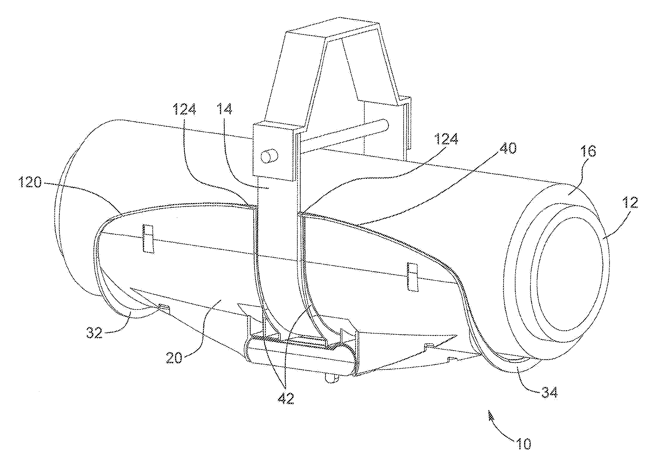
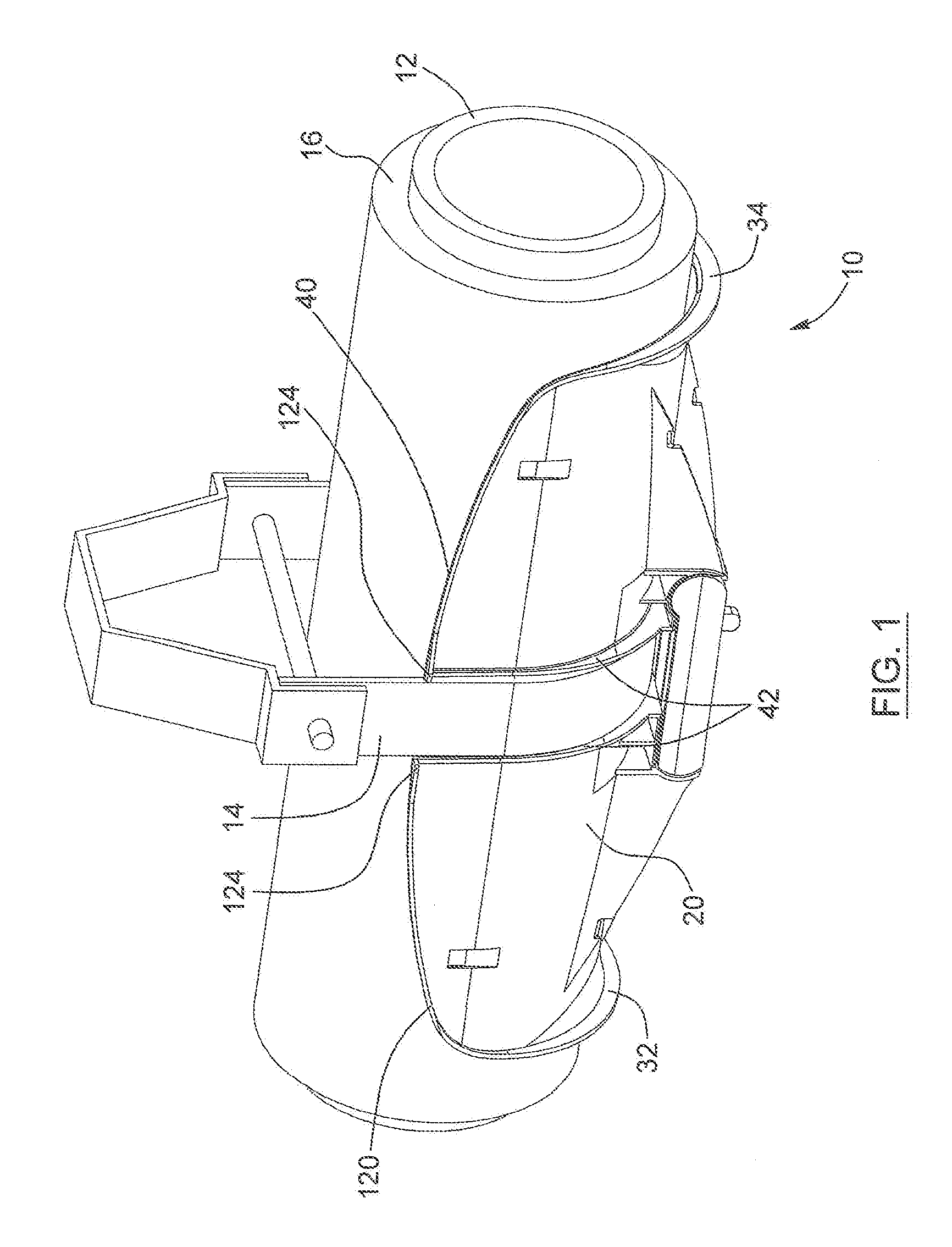
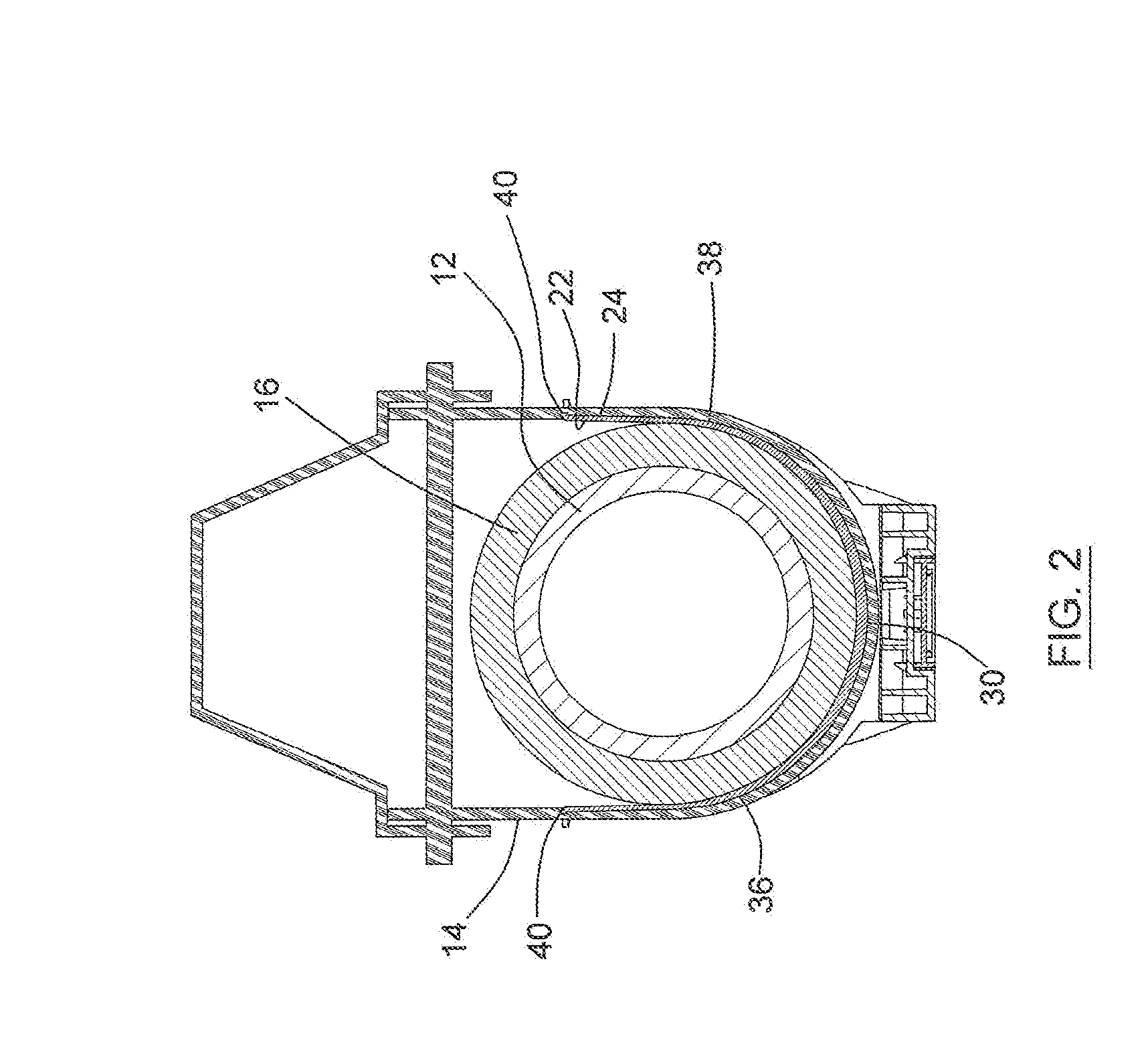
[0039]In the following description, the same numerical references refer to similar elements. The embodiments, geometrical configurations, materials mentioned and / or dimensions shown in the figures or described in the present description are preferred embodiments only, given solely for exemplification purposes.

[0040]Moreover, although the preferred embodiment of the pipe support and corresponding parts thereof consist of certain geometrical configurations as explained and illustrated herein, not all of these components and geometries are essential to the invention and thus should not be taken in their restrictive sense, i.e. should not be taken as to limit the scope of the present invention. It is to be understood, as also apparent to a person skilled in the art, that other suitable components and cooperation thereinbetween, as well as other suitable geometrical configurations, may be used for the pipe support according to the present invention, as will be briefly explained herein an...


PUM


Abstract

A pipe support for supporting a horizontally extending pipe in combination with a vertical hanger. The pipe support comprises a U-shaped body being opened at a top end thereof. The pipe support also comprises a pair of transversal vertical ribs, located on the outer surface of the body and extending transversally to an axis formed between the extremities of the body. The pair of transversal vertical ribs forms a space to receive the hanger therebetween, the space being positioned between the first and second extremities of the body. The pipe support further comprises a shock detection mechanism attachable to the pipe support. The shock detection mechanism comprises a shock indicator movable between a hold position and an alert position indicative that the pipe support was subjected to a shock exceeding a predetermined threshold force. A pipe support kit is also provided according to the present invention.

Description

FIELD OF THE INVENTION[0001]The present invention relates to a pipe support. More particularly, it relates to a pipe support providing enhanced support to pipes extending horizontally, being easy to install and allowing shock detection. A kit for providing the same is also provided.BACKGROUND OF THE INVENTION[0002]In commercial and industrial constructions, horizontally running pipe systems are most commonly supported using a series of U-shaped pipe supporting members, such as clevis hangers, affixed to the ceiling or to any other overhead surface, and disposed at variable distances.[0003]The pipe conduits often convey material at a temperature substantially higher or lower from the ambient temperature. In such cases, the pipe conduits usually require thermal insulation in order to prevent changes in the temperature of the conveyed material, due to heat transfer occurring at the pipe surface. Thermal insulation is also very effective in preventing the formation of condensation at th...

Claims


Application Information

Patent Timeline
IPC IPC(8): F16L3/00E21F17/02
CPCF16L59/135G01L5/0052F16L55/035
Inventor MONTPLAISIR, CHRISTIANBOUDREAU, MARTIN
Owner ARMACELL ENTERPRISE GMBH & CO KG
Why Eureka
Try Eureka