Two-lip rubber seal with reinforcement

a two-lip rubber and reinforcement technology, applied in the direction of engine seals, yielding couplings, engine components, etc., can solve the problems of slipping of slipping into the inner region, and slipping up to 0.3 mm of the housing lid relative to the outer ring, so as to improve the resistance to slipping

Inactive Publication Date: 2012-10-30
IFA TECH
View PDF8 Cites 5 Cited by
  • Summary
  • Abstract
  • Description
  • Claims
  • Application Information

AI Technical Summary

Benefits of technology

[0010]It is therefore an object of the invention to provide a seal for sealing an outer ring, which provides improved resistance to slipping in normal operation of a cardan shaft.
[0013]The second sealing element, which is also connected to the shape-stabilizing element, represents a certain redundancy with regard to the sealing function of the seal, and furthermore stabilizes the seat of the seal between the outer ring and a housing lid, due to the connection to the shape-stabilizing element.
[0014]In another embodiment of the seal according to the invention, the shape-stabilizing element is disposed in the contact surface plane between the first sealing element and the second sealing element. Preferably, the shape-stabilizing element can engage into each of the sealing elements in order to produce the firm connection. By placing the shape-stabilizing element between the sealing elements, the result is achieved that the two sealing elements follow the shape of the shape-stabilizing element, in other words the desired progression in the contact surface plane to be sealed, without additional guide aids fundamentally being required. However, it can certainly be practical and advantageous to surround the seal with a stop edge in the region that lies toward the outside, radially away from the axis of symmetry of the cardan shaft, in order to simplify its positioning, particularly during assembly, but also in the assembled state.
[0015]In another practical embodiment of the seal according to the invention, the shape-stabilizing element has a smaller thickness, in its expanse that extends perpendicular to the sealing surface, than that of the individual sealing elements. Because of the thinner configuration of the shape-stabilizing element, it does not participate in the sealing effect of the seal as a whole, but rather merely serves for shape stabilization of the sealing elements. The torsion forces and thermal displacement forces that were described above as being disadvantageous thus affect the shape stabilization element only insignificantly, so that its progression is not significantly influenced. The sealing elements, which are generally squeezed between the surfaces to be sealed relative to one another in the assembled state, take over the redundant sealing effect, as already described.
[0017]In another embodiment of the seal according to the invention, it has a reinforcement as a shape-stabilizing element, which can preferably be configured as a light-metal or steel or plastic ring, and, in particular, has a U shape in cross-section. Metal or plastic rings primarily have a particularly greater strength and, resulting from this, an extremely good shape stability, so that the shape-stabilizing properties of such a metal or plastic ring hold the sealing elements connected to it in their intended position. By means of the U-shaped structure, the metal ring can engage into the sealing elements with its two U shanks, holds them, or brings them to desired positions.

Problems solved by technology

In ongoing operation, particularly during transfer of engine forces, the housing of the cardan shaft occasionally experiences greater torque surges, which can individually lead to a slip of up to 0.3 mm of the housing lid relative to the outer ring.
Because of the torque surges and the thermal material expansion, particularly when using different materials, there is always the problem, in conventional seals, that they can slip, and project into the inner region of the outer ring, in other words into the joint mechanism, for example.
As the result of such a problem, a leak occurs, for one thing, which leads to a constant loss of the lubricant medium—in the long term, the joint fails as a result.

Method used


Image

  • Two-lip rubber seal with reinforcement
  • Two-lip rubber seal with reinforcement
  • Two-lip rubber seal with reinforcement

Examples


Embodiment Construction

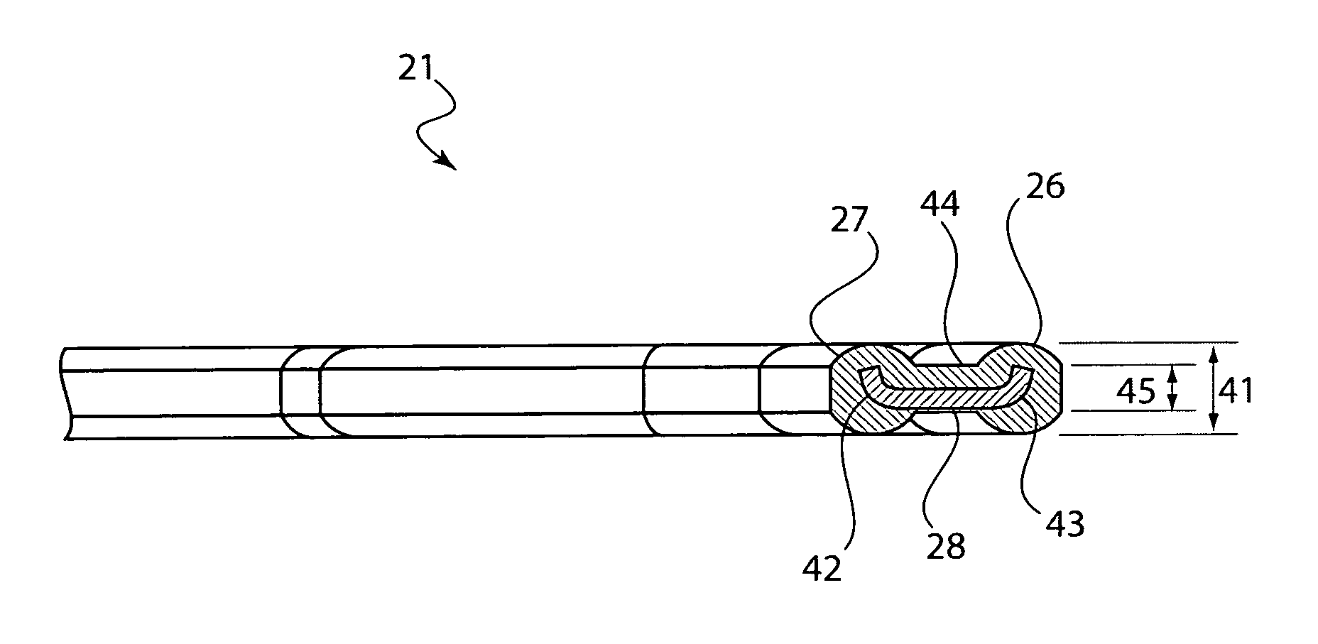
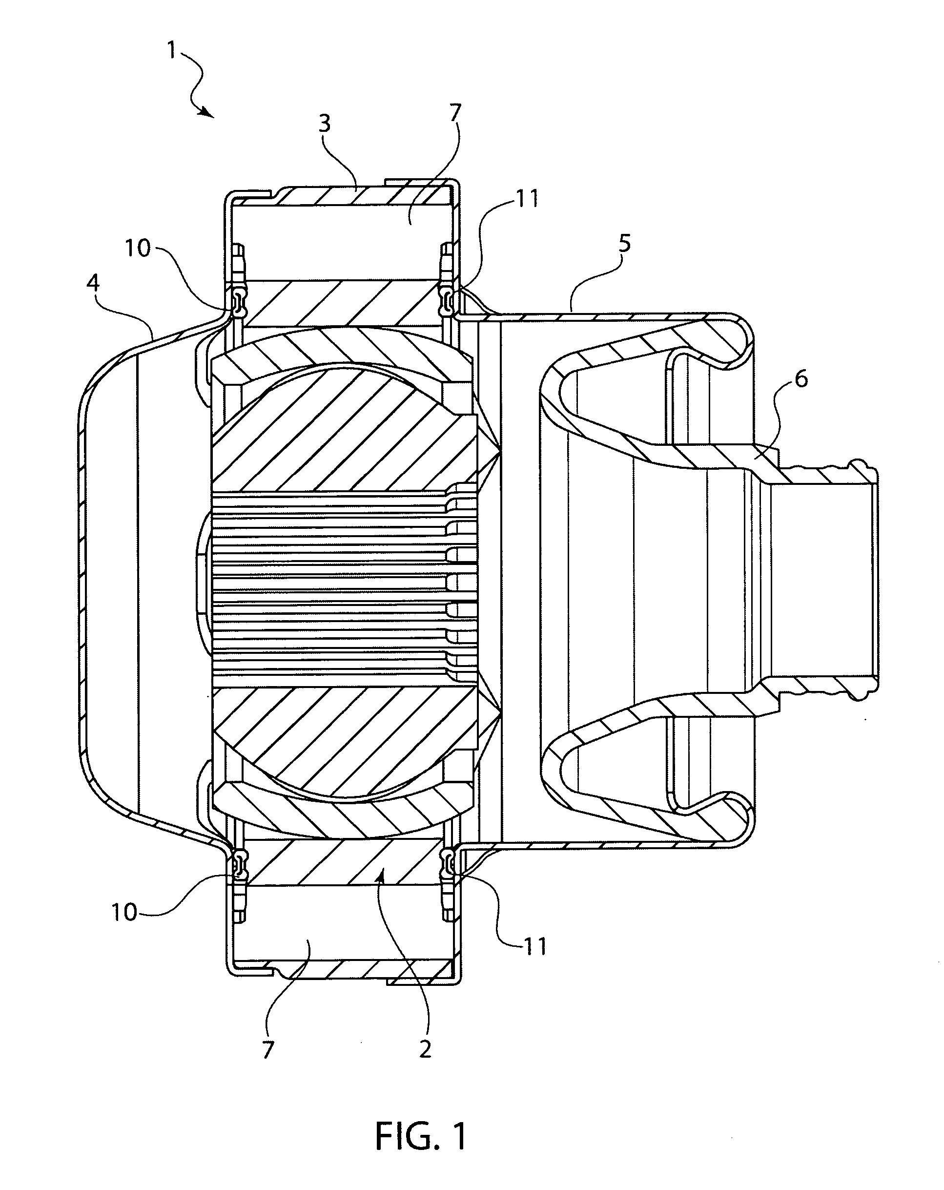
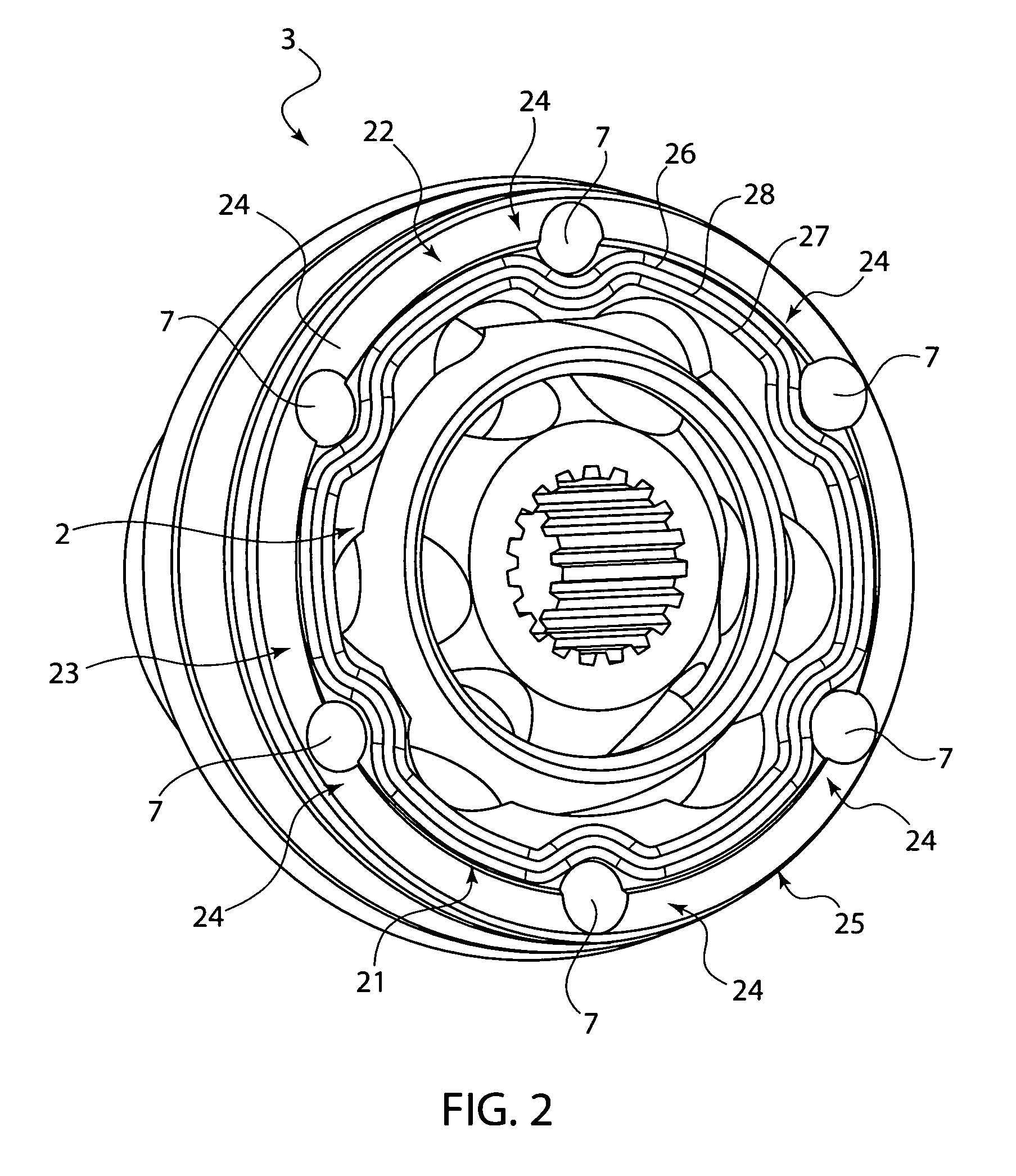
[0027]Referring now in detail to the drawings, FIG. 1 shows a cardan shaft 1 according to the invention, which comprises an outer ring 3 that accommodates a joint 2 and is configured as a corpus element. On both sides, outer ring 3 is closed off by a lid 4 on the transmission side and a lid 5 with joint cuff 6 for passing through the power take-off shaft (not shown here). The two lids 4 and 5 are attached to outer ring 3 by screw connections, which pass through outer ring 3 through a screw channel 7, and are braced relative to the ring. Outer ring 3 has circumferential seals that lie within screw channel 7, viewed relative to joint 2, which comprise a seal 10 between lid 4 on the transmission side and the contact surface of outer ring 3, and a seal 11 between lid 5 on the power take-off side and outer ring 3, on the contact surface. The surfaces of outer ring 3 and of lid 4 or 5 which run parallel to one another in the sealed state and between which seals 10 and 11, respectively, ar...


PUM


Abstract

A seal for sealing a cardan shaft housing, particularly at a contact surface between an outer ring and a housing lid, has a first sealing element that at least partially covers the contact surface plane to be sealed, as well as a first shape-stabilizing element that is at least partially firmly connected with the first sealing element. A second sealing element is at least partially firmly connected on the shape-stabilizing element.

Description

CROSS REFERENCE TO RELATED APPLICATIONS[0001]Applicant claims priority under 35 U.S.C. 119 of German Application No. 10 2009 018 373.6 filed Apr. 23, 2009.BACKGROUND OF THE INVENTION[0002]1. Field of the Invention[0003]The invention relates to a seal for sealing a constant velocity joint as well as a correspondingly sealed cardan shaft.[0004]2. The Prior Art[0005]There are several applications for cardan shafts and / or constant velocity joints in the sector of technical mechanical engineering. Force-transferring constant velocity joints are used in the automotive industry, in which the cardan shaft is used between the power take-off of the transmission and the drive train.[0006]A cardan shaft according to the state of the art is generally composed of an outer ring that accommodates the joint mechanism, which ring is configured as a corpus element that accommodates the joint, and at least one lid that closes off the outer ring with regard to the surroundings. Passages for correspondin...

Claims


Application Information

Patent Timeline
Patent Type & Authority Patents(United States)
IPC IPC(8): F16J15/12
CPCF16D3/223F16J15/122F16D3/845
Inventor SCHMID, REINER
Owner IFA TECH
Why Eureka
Try Eureka