Mould with easy-replaceable mould plates

a mould plate and replaceable technology, applied in the field of moulds with replaceable mould plates, can solve the problems of increasing manufacturing costs and inconvenient replacement of mould plates, and achieve the effects of convenient user assembly and disassembly of mould plates, reducing production costs, and quick replacemen

Active Publication Date: 2012-10-30
YANG TENG JEN
View PDF7 Cites 8 Cited by
  • Summary
  • Abstract
  • Description
  • Claims
  • Application Information

AI Technical Summary

Benefits of technology

[0006]The primary objective of the present invention is to provide a mould apparatus with replaceable mould plates through which the user can quickly replace the mould plates, enhancing the convenience in use, and the new mould plates can be applied to the original mould bases as long as they are formed with guide grooves for cooperating with the positioning units, greatly reducing the production cost.
[0017]Since the respective mould plates are formed with guide grooves for cooperating with the pressing elements of the positioning units, the respective mould plates can be slidably assembled on the mould bases, making it convenient for the user to assemble and disassemble the mould plates. Meanwhile, since the mould plates can be quickly replaced, when different products are going to be produced, it only needs to redesign new mould plates with new forming blocks, and the new mould plates can also be applied to the original mould bases as long as they are formed with the guide grooves for cooperating with the positioning portions of the positioning units. That is to say that only the mould plates should be changed and the mould bases can still be used when different types of products are produced, greatly reducing the production cost while producing high economic benefits.

Problems solved by technology

For example, when new products are to be manufactured, a new mould must be designed and manufactured, thus increasing the manufacturing cost.
In addition, if the mould has a large volume, the replacement of the mould is quite inconvenient due to the use of large-scale machines such as crane.

Method used


Image

  • Mould with easy-replaceable mould plates
  • Mould with easy-replaceable mould plates
  • Mould with easy-replaceable mould plates

Examples


Embodiment Construction

[0027]The present invention will be clearer from the following description when viewed together with the accompanying drawings, which show, for purpose of illustrations only, the preferred embodiment in accordance with the present invention.

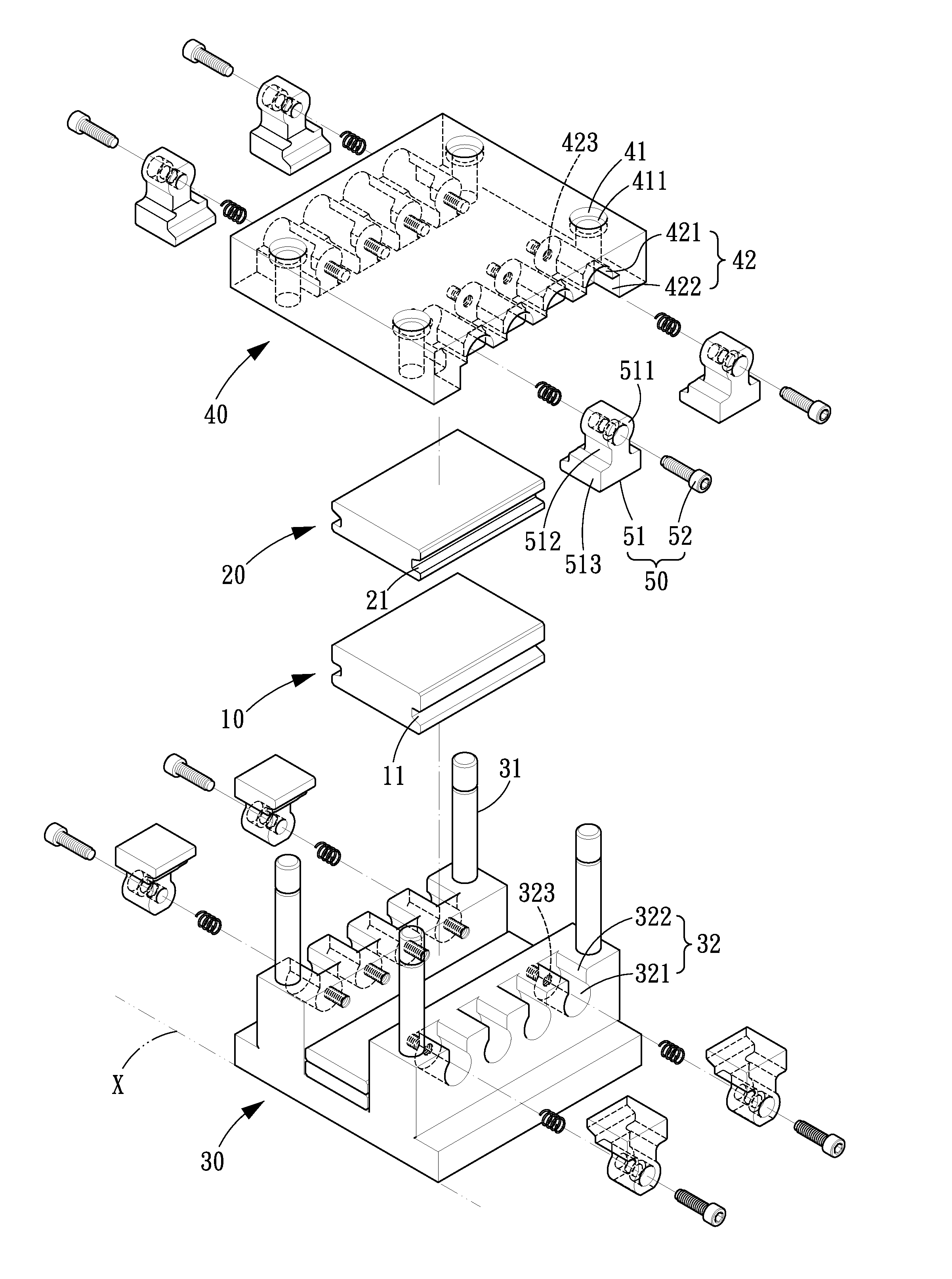
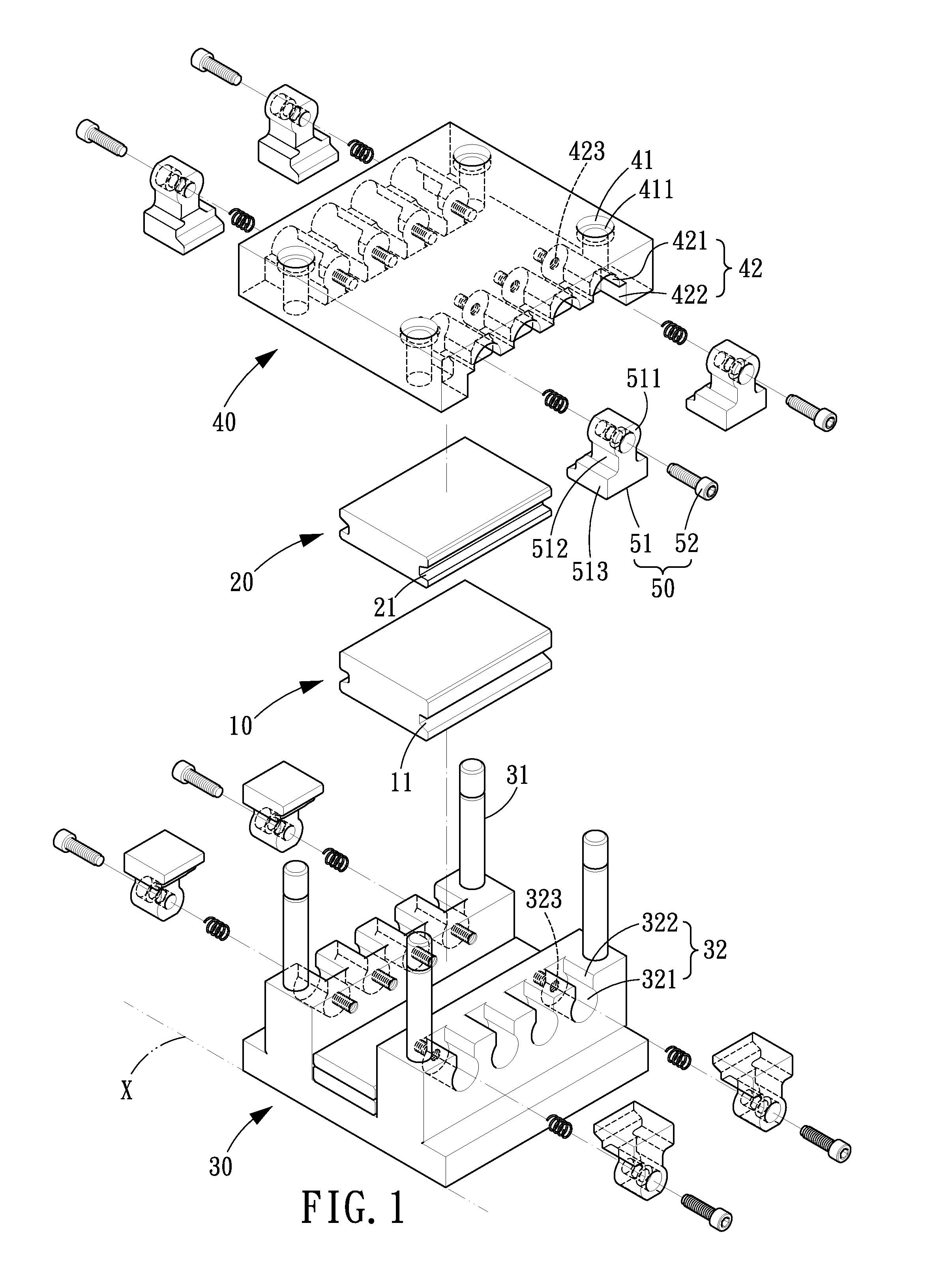
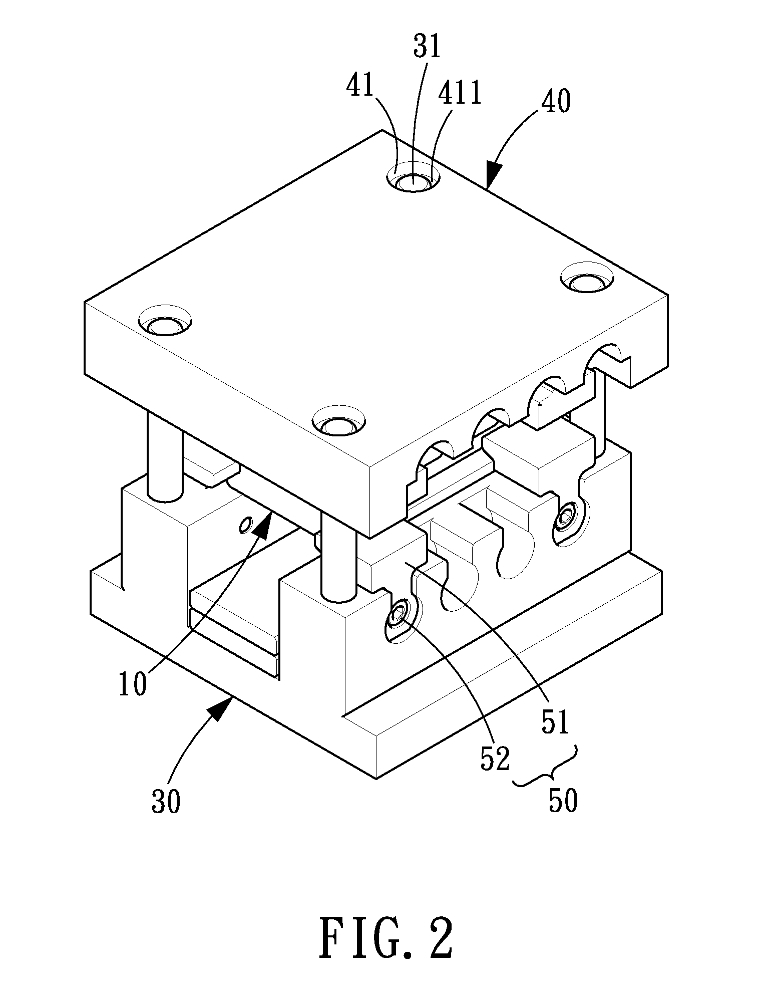
[0028]Referring to FIGS. 1-6, a mould apparatus with replaceable mould plates in accordance with a preferred embodiment of the present invention is provided for positioning a first mould plate 10 and a second mould plate 20, and the mould comprises a first mould base 30, a second mould base 40, and plural positioning units 50.

[0029]The first mould base 30 is parallel to a datum plane X and provided with a limiting pin 31 at each of four corners on an upper surface thereof. The four limiting pins 31 extend in a direction vertical to the datum plane X. The first mould base 30 in the present embodiment is formed with plural assembling grooves 32 in each of two opposite sides thereof. The respective assembling grooves 32 include a curved guide portio...


PUM

PropertyMeasurementUnit
volumeaaaaaaaaaa
pressing forceaaaaaaaaaa
pressureaaaaaaaaaa

Abstract

A mold apparatus with replaceable mold plates comprises mold bases, and positioning units used to position mold plates on the respective mold bases. If the positioning units are removed, the mold plates can be easily replaced in such a manner that the mold plates are made to slide along the positioning units, facilitating the replacement of the mold plates. Since the mold plates can be quickly replaced, when different products are going to be produced, it only needs to redesign new mold plates with new forming blocks, and the new mold plates can also be applied to the original mold bases as long as they are formed with the guide grooves for cooperating with the positioning portions of the positioning units, greatly reducing the production cost while producing high economic benefits.

Description

BACKGROUND OF THE INVENTION[0001]1. Field of the Invention[0002]The present invention relates to a plastic injection mould, and more particularly to a mould apparatus with replaceable mould plates.[0003]2. Description of the Prior Art[0004]Plastic injection molding is a forming method suitable for mass production with stable quality, so that the plastic injection molding is widely applied in various fields. To manufacture a product, an exclusive mould should be designed in advance, and in order to be assembled on an injection molding machine, the mould generally consists of a mould base and a mould plate so that the mould plate can be disposed on the mould base while the mould base is disposed on the machine. Moreover, since the mould plate and the mould base are exclusively configured for corresponding products, they must be replaced together when necessary. For example, when new products are to be manufactured, a new mould must be designed and manufactured, thus increasing the man...

Claims


Application Information

Patent Timeline
Patent Type & Authority Patents(United States)
IPC IPC(8): B29C45/10
CPCB29C33/305B29C45/2673
Inventor YANG, TENG-JEN
Owner YANG TENG JEN
Why Eureka
Try Eureka