Driving device for an electric lock latch

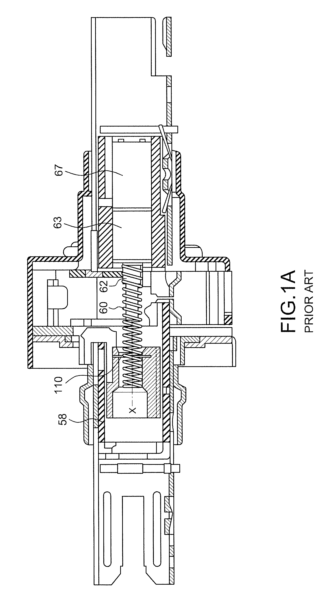
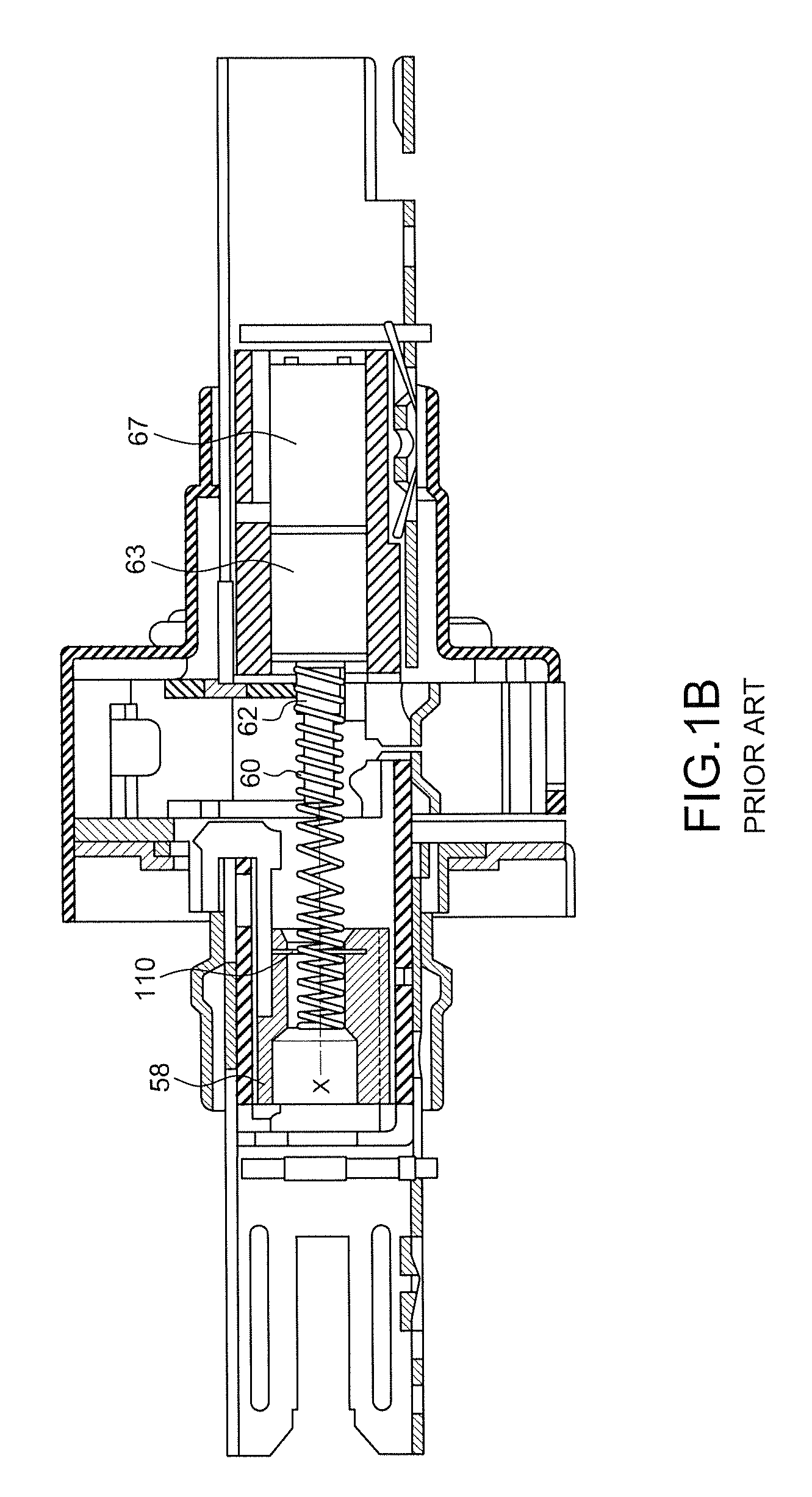
a technology of driving device and electric lock, which is applied in the direction of lock applications, gearing, hoisting equipment, etc., can solve the problems of complicated installation of roll pin and drive pin according to u.s. pat. no. 6,076,870, and large power consumption for activating electromagnetic valves

Active Publication Date: 2012-11-06
LUI PANG CHENG
View PDF19 Cites 35 Cited by
  • Summary
  • Abstract
  • Description
  • Claims
  • Application Information

AI Technical Summary

Benefits of technology

[0010]An object of the invention is to eliminate the above-mentioned drawbacks of the conventional equal diameter spring driven by a pin and to provide a driving device with an unequal diameter coil spring for an electric lock latch, wherein the middle part of the unequal diameter coil spring has a cylindrical spiral with a smaller diameter in threaded connection to an external thread of a drive shaft. Moreover, the internal and external parts of the spiral spring have a larger diameter, such that no threaded connection to the drive shaft is established. In other words, the drive shaft corresponding to the internal and external parts of the unequal diameter coil spring will be idling in order to protect the unequal diameter coil spring from damage of over-compression or over-extension.
[0011]Another object of the invention is to provide a driving device for an electric lock latch that can be easily modularized and applied to all kinds of lock devices. Accordingly, the lock structure and the installation thereof may be simplified.

Problems solved by technology

However, the activation of the electromagnetic valve requires a large power consumption.
As a result, the installer must have the electronic knowledge and the installation skill, thereby causing much difficulty for the installer.
Moreover, the installation of the roll pin and the drive pin according to the U.S. Pat. No. 6,076,870 is complicated.
Based on the features disclosed in U.S. Pat. No. 5,628,216, the spring 60 rotates with the shaft of a motor 67, such that the spring 60 may be excessively compressed or may be excessively extended, resulting in an elastic fatigue and a high breakdown.

Method used


Image

  • Driving device for an electric lock latch
  • Driving device for an electric lock latch
  • Driving device for an electric lock latch

Examples


Embodiment Construction

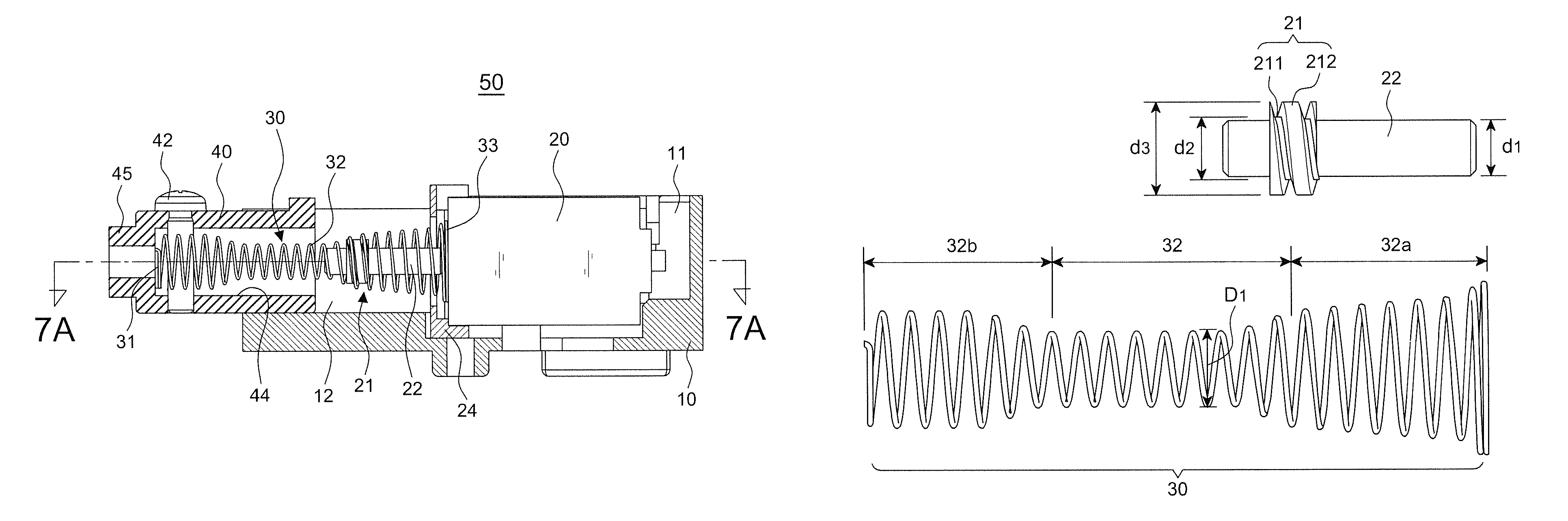
[0034]Referring to FIGS. 2 through 8, the preferred embodiment of a driving device 50 in accordance with the present invention comprises a housing 10, a motor 20, an unequal diameter coil spring 30, and a lock latch 40.

[0035]The housing 10 may be set into different shape. In this embodiment, the housing 10 with an opening on the top has a recessed accommodation slot 11 and a sliding slot 12 therein.

[0036]The motor 20 positioned within the recessed accommodation slot 11 of the housing 10 has a power output shaft 23 connected to a drive shaft 22 with an external thread 21 on a part thereof. With reference to FIG. 6, a diameter d2 of a root 211 of the external thread 21 is larger than a diameter d1 of the drive shaft 22.

[0037]The unequal diameter coil spring 30 as shown in FIG. 6 has a cylindrical spiral 32 in a middle section thereof. A rotation sense of the unequal diameter coil spring 30 such as left rotation or right rotation is the same as of the external thread 21. Moreover, an a...


PUM


Abstract

A driving device for an electric lock latch, comprises a housing, a motor having a power output shaft connected to a drive shaft with an external thread on a part thereof, an unequal diameter coil spring having a cylindrical spiral in the middle thereof screwing with the drive shaft, and a first and second conical spiral on both end thereof not screwing with the drive shaft, and a lock latch secured to the second conical spiral. The drive shaft is driven and rotated by a motor to pass the rotation power to the cylindrical spiral, and a rotary motion of the drive shaft is converted into a linear motion of the unequal diameter coil spring for moving the lock latch to change the locked and unlocked state of the lock device. Accordingly, the lock structure and the installation thereof may be simplified and the power-saving effect is achieved.

Description

[0001]This patent application is a continuation-in-part of Ser. No. 12 / 591,169, filed on 12 Nov. 2009, currently pending.BACKGROUND OF THE INVENTION[0002]1. Field of the Invention[0003]The invention relates to a driving device for an electric lock latch, and more particularly to a structure with a drive shaft having an external threaded for driving an unequal diameter spiral spring in threaded connection thereto. Moreover, the lock latch is connected at the external part of the spiral spring. As a result, the circular motion of the drive shaft is converted into the rectilinear motion of the spiral spring such that the lock latch is moved. In this way, the locked and unlocked state of the lock device may be changed by the movement of the lock latch. Moreover, the structure of the invention can be applied to all kinds of lock devices.[0004]2. Description of the Related Art[0005]It is quite normal that the lock employs an electromagnetic valve to control the movement of the latch, ther...

Claims


Application Information

Patent Timeline
Patent Type & Authority Patents(United States)
IPC IPC(8): E05B47/00
CPCE05B47/0012E05B47/0692E05B47/0673Y10T74/1973E05B2015/0406E05B2015/0496E05B2047/0031E05B47/0661Y10T74/19721Y10T74/18576Y10T74/1868Y10T74/19712Y10T74/18312Y10T74/19702Y10T74/19633Y10T70/7062Y10T70/7102Y10T70/7107Y10T70/7113Y10T70/713
Inventor LUI, PANG-CHENG
Owner LUI PANG CHENG
Why Eureka
Try Eureka